background image

AP-6511 Access Point  

Installation Guide


38

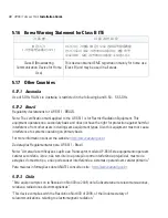
5.16    Korea Warning Statement for Class B ITE

5.17    Other Countries

5.17.1    Australia

Use of 5 GHz RLAN’s in Australia is restricted in the following band 5.50 – 5.65 GHz.

5.17.2    Brazil

Regulatory declarations for AP-6511 - BRAZIL

Note: The certification mark applied to the AP-6511 is for Restrict Radiation Equipment. This 
equipment operates on a secondary basis and does not have the right for protection against harmful 
interference from other users including same equipment types. Also this equipment must not cause 
interference to systems operating on primary basis. 

For more information consult the website 

http://www.anatel.gov.br

Declarações Regulamentares para AP-6511 - Brasil

Nota: "A marca de certificação se aplica ao  Transceptor, modelo AP-650. Este equipamento opera em 
caráter secundário, isto é, não tem direito a proteção contra interferência prejudicial, mesmo de 
estações do mesmo tipo, e não pode causar interferência a sistemas operando em caráter primário.”

Para maiores informações sobre ANATEL consulte o site:  

http://www.anatel.gov.br

5.17.3    Chile

“Este equipo cumple con la Resolución No 403 de 2008, de la Subsecretaria de telecomunicaciones, 
relativa a radiaciones electromagnéticas.”.

"This device complies with the Resolution Not 403 of 2008, of the Undersecretary of 
telecommunications, relating to electromagnetic radiation.”  


기 종 별


사 용 자 안 내 문

B 급 기기


( 가정용 방송통신기기 )

이 기기는 가정용 (B 급 ) 으로 전자파적합등록을

한 기기로서 주로 가정에서 사용하는 것을 목적
으로 하며 , 모든 지역에서 사용할 수 있습니다 .

Class B (Broadcasting 

Communication Device for Home 

Use) 

This device obtained EMC registration mainly for home use 
(Class B) and may be used in all areas.

Summary of Contents for AP-6511

Page 1: ...AP 6511 Access Point Installation Guide M ...

Page 2: ...ogo are registered in the US Patent Trademark Office Sym bol is a registered trademark of Symbol Technologies Inc All other product or service names are the property of their respective owners Motorola Inc 2010 All rights reserved ...

Page 3: ...allation Instructions 4 2 2 Precautions 4 2 3 Access Point Placement 5 2 4 Power Injector System 5 2 5 Wall Mount Instructions 6 2 6 Telco Box Installation 9 2 7 AP 6511 Antennas 14 2 8 LED Indicators 14 3 Defining a Basic AP 6511 Configuration 15 4 Specifications 29 5 Regulatory Information 31 6 Motorola s Enterprise Mobility Support Center 41 Table of Contents ...

Page 4: ...to the wall plate The AP 6511 Access Point ships with a single dual band radio supporting the 802 11a b g n radio bands The AP 6511 Access Point receives all power and transfers data through the same CAT 5 or better Ethernet cable There is no additional power supply required An 802 3af PoE Ethernet switch or mid span power injector is required The AP 6511 can be ordered for US deployment AP 6511 6...

Page 5: ...ontents The AP 6511 model Access Point ships with internal integrated antennas AP 6511 Access Point Mounting plate used for both wall mount and Telco Box installations Mounting plate lock screw AP 6511 Installation Guide This Guide RJ 45 double plug interconnect cable Fast Ethernet port 1 interconnect cable 1 5 Features One RJ 45 PoE Ethernet port built into the AP 6511 access point Optional secon...

Page 6: ...ector A three port RJ 45 Ethernet expansion module connects to the hidden header and snaps onto the AP 6511 in place of the access cover Remove the AP 6511 s access cover by using a sharp tool to depress the latch on the bottom of the access point Pull the access cover up and away from the AP 6511 Reverse the procedure to install the expansion module The Ethernet expansion module has three ports l...

Page 7: ...nts of the box include the intended AP 6511 Access Point model and the included hardware matches the package contents on page 2 3 Review site survey and network analysis reports to determine the location and mounting position for the AP 6511 Access Point 4 Connect a CAT 5 or better Ethernet cable to a PoE compatible device and run the cable to the installation site Ensure there is sufficient cable...

Page 8: ...s Point placement in respect to the intended coverage area The Motorola Power Injector Part No AP PSBIAS 1P2 AFR is the recommended 802 3af compatible power supply for the AP 6511 The Power Injector is capable of providing 12 95 Watts up to 100 meters The Power Injector is separately ordered and not shipped with the AP 6511 A separate Power Injector is required for each Access Point comprising the...

Page 9: ...ttach the metal mounting plate shipped with the AP 6511 to a wall surface at the desired deployment location CAUTION To avoid problematic performance and restarts disable POE from a wired controller port connected to an Access Point if mid span power sourcing equipment PSE is used between the two regardless of the manufacturer CAUTION Ensure AC power is supplied to the Power Injector using an AC c...

Page 10: ...stallation 7 The screws used to mount the bracket are customer provided and should be 6 with a 2 00 inch length 2 Connect one end of an RJ 45 cable into the wall mount connector on the AP 6511 as illustrated below ...

Page 11: ...connected securely c Remove the blank plug from the keystone hole by gently pushing it out from the back d Orient the RJ 45 keystone connector so the flexible keystone tab is away from the mini pin connector Tip the keystone RJ 45 while installing in the keystone opening so the solid locking tabs engage then rotate the RJ 45 forward until the tab snaps securely 4 Snap the AP 6511 on to the mounted...

Page 12: ...e Power Injector has no On Off power switch The Power Injector receives power as soon as AC power is applied For more information see Power Injector System on page 5 6 Verify the behavior of the AP 6511 Access Point LEDs For more information see LED Indicators on page 14 7 The AP 6511 is ready to configure For information on basic Access Point device configuration see Defining a Basic AP 6511 Conf...

Page 13: ... Installation Guide 10 1 Remove the cover of the CAT5 wall plate 2 Snap out keystone connectors from existing plate NOTE The example above assumes the Telco Box has a 1 RJ11 phonejack and 1 RJ 45 10 100 Ethernet connection ...

Page 14: ...l mounting plate shipped with the AP 6511 to an existing standard Telco in wall box The screws used to mount the bracket to the Telco Box are customer provided You can use the same screws that are covered the existing wall plate if necessary Mount the AP 6511to the wall so the Telco Box is ready available behind the mounting plate ...

Page 15: ...he mini pin connector into the pin socket on the back of the AP 6511 The connector is keyed and can only be installed one way Ensure the mini pin connector is connected securely c Remove the blank plug from the keystone hole by gently pushing it out from the back d Orient the RJ 45 keystone connector so the flexible keystone tab is away from the mini pin connector Tip the keystone RJ 45 while inst...

Page 16: ...e Power Injector s Data In connector b Connect an RJ 45 CAT5 Ethernet cable between the Power Injector s Data Power Out connector and the AP 6511 Access Point c Ensure the cable length from the Ethernet source host to the Power Injector and Access Point does not exceed 100 meters 333 ft The Power Injector has no On Off power switch The Power Injector receives power as soon as AC power is applied F...

Page 17: ...indicators on the front of the unit The LEDs provide a status display indicating error conditions transmission and network activity for the 5 GHz 802 11a n amber radio or the 2 4 GHz 802 11b g n green radio Task 5 GHz Activity LED Amber 2 4 GHz Activity LED Green Unadopted Off Blinking 5 times per second Normal Operation If this radio band is enabled Blink at 5 second interval If this radio band i...

Page 18: ...However if a DHCP server is not available you ll need to derive the IP address from the AP 6511 MAC address Using this method the last two bytes of the AP 6511 MAC address become the last two octets of the IP address AP 6511 MAC address 00 C0 23 00 F0 0A AP 6511 IP address equivalent 169 254 240 10 To derive the AP 6511 s IP address using its factory assigned MAC address a Open the Windows calcula...

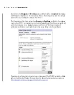
Page 19: ...d or adopted by a Controller AP the Initial Setup Wizard no longer displays in subsequent logins NOTE When navigating the Initial Setup Wizard the left hand side of the Wizard can either display a topology Diagram or an Event Log of the tasks completed or failed during the AP 6511 configuration Motorola recommends periodically reviewing the topology and log to assess whether the tasks completed th...

Page 20: ...autonomous Access Point Dependent AP Select this option when deploying the AP 6511 as a Controller AP managed Access Point Selecting this option closes the Initial Setup Wizard A Dependant AP obtains its configuration from a profile stored on the Controller AP Any manual configuration changes on a Dependant AP are overwritten by the Controller AP upon reboot A Dependent AP requires a Controller AP...

Page 21: ...P 6511 s deployment area and the Contact accurately reflects the administrator responsible for this AP 6511 Access Point 10 Set a Time Zone and Country Both the Time Zone and Country should reflect the actual deployment credentials of this AP 6511 to best assist in any troubleshooting of the device that may be needed 11 Select any or all of access methods HTTP HTTPS Telnet or SSHv2 used for connec...

Page 22: ...routes traffic between the local network LAN and internet or external network WAN Bridge Mode In Bridge Mode the AP 6511 depends on an external router for routing LAN and WAN traffic Routing is generally used on one device whereas bridging is typically used for a larger density network For the purposes of this guide Router Mode is selected as Bridge Mode does not require that all parameters be set...

Page 23: ...ckbox is selected this field is not available Use DHCP Select the checkbox to enable an automatic network configuration using a DHCP server If this option is enabled the LAN IP Address Subnet DHCP Address Assignment and Domain Name fields are populated by the DHCP server What VLAN ID should be used for the LAN interface Use the spinner to select the VLAN ID to associate with the LAN Interface The ...

Page 24: ...rd DHCP server to provide IP and DNS information to clients on the LAN interface IP Address Range Enter a starting and ending IP Address range for client assignments on the LAN interface Avoid assigning IP addresses from x x x 1 x x x 10 and x x x 255 as they are often reserved for standard network services 17 Set the following Domain Name Server information Primary DNS Enter an IP Address for the...

Page 25: ...s Subnet and Gateway fields are populated by the DHCP server What VLAN ID should be used for the WLAN interface Use the spinner to select the VLAN ID to associate with the WAN Interface The default setting is VLAN 2100 What port is connected to the external network Use the drop down menu to select the physical port that s connected to the WAN interface Enable NAT on the WAN Interface Select the ch...

Page 26: ...LAN Captive portal authentication no encryption for a guest WLAN PSK authentication WPA2 encryption to implement a pre shared key or EAP authentication WPA2 encryption to implement an external RADIUS server VLAN ID Use the drop down menu to select a VLAN for traffic segregation on this WLAN All configured VLANs are available WPA Key Enter an alphanumeric string of 8 to 63 ASCII characters or 64 HE...

Page 27: ...RADIUS Shared Secret Specify a Shared Secret for authenticating RADIUS requests to access a AP 6511 managed WLAN Shared secrets verify RADIUS messages from RADIUS enabled devices configured with the same secret passphrase 25 Select Commit Next to save the updates to the RADIUS Authentication screen and display the AP Discovery screen The AP Discovery screen lists Access Points discovered by this A...

Page 28: ...discovered by this AP 6511 Defining hostnames is a good practice to differentiate discovered APs with similar configurations 26 Select Next to continue to the Wireless Client Association screen The Wireless Client Association screen displays adopted wireless clients and the AP 6511 WLANs they are currently connected to ...

Page 29: ...ify the WLAN s configuration associate a client with each configured WLAN After associating click the Refresh button to update the list of associated wireless clients 28 Select Save Next to commit any changes made and continue to the Date and Time screen ...

Page 30: ...meter to define an external NTP server resource to periodically synchronize system time with this AP 6511 If manually providing system time select the Update Clock button to commit the system time to the AP 6511 If using an external NTP resource provide its numerical IP address and select the Update NTP button 30 Select Finish to complete the AP 6511 Initial Setup Wizard Once complete a configurat...

Page 31: ...and Settings modified by the updates made to the AP 6511 configuration using the Initial Setup Wizard Scroll to any screen listed within the Complete tab to display that screen within the AP 6511 user interface if additional modifications are required beyond the scope of the Initial Setup Wizard For advanced configuration information beyond the scope of this AP 6511 Installation Guide refer to the...

Page 32: ...ns 2 75 width x 5 height x 1 25 deep Inches 6 985 width x 12 7 height x 3 175 deep centimeters Housing Plastic and metal Weight 0 5 lbs with mounting plate Operating Temperature 32 F to 104 F 0 C to 40 C Storage Temperature 40 F to 158 F 40 C to 85 C Operating Humidity 5 to 95 Relative Humidity non condensing Storage Humidity 95 Relative Humidity non condensing Operating Altitude max 8 000 ft 28 C...

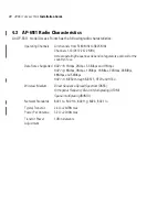
Page 33: ...pproval for the country of use Data Rates Supported 802 11b 1Mbps 2Mbps 5 5Mbps and 11Mbps 802 11g 6Mbps 9Mbps 12Mbps 18Mbps 24Mbps 36MBps 48Mbps and 54Mbps 802 11n MCS0 through MCS15 HT20 and HT40 Wireless Medium Direct Sequence Spread Spectrum DSSS Orthogonal Frequency Division Multiplexing OFDM Spatial multiplexing MIMO Network Standards 802 11a 802 11b 802 11g 802 3 802 11n Typical Transmit Po...

Page 34: ...e supplied or an approved replacement antenna Unauthorized antennas modifications or attachments could cause damage and may violate regulations Use of an unapproved antenna is illegal under FCC regulations subjecting the end user to fines and equipment seizure 5 2 Wireless Device Country Approvals Regulatory markings subject to certification are applied to the device signifying the radio s is are ...

Page 35: ...of transmitting in the band 5600 5650 MHz in the US this Notched band has been disabled in the US version of the Access Point 2 4 GHz Only The available channels for 802 11 b g operation in the US are Channels 1 to 11 The range of channels is limited by firmware 5 3 Health and Safety Recommendations 5 3 1 Warnings for the use of Wireless Devices Please observe all warning notices with regard to th...

Page 36: ...ufacturer of the medical device to determine if the operation of your wireless product may interfere with the medical device 5 4 RF Exposure Guidelines 5 4 1 Safety Information Reducing RF Exposure Use Properly Only operate the device in accordance with the instructions supplied 5 5 International The device complies with internationally recognized standards covering human exposure to electromagnet...

Page 37: ...e reasonable protection against harmful interference in a residential installation This equipment generates uses and can radiate radio frequency energy and if not installed and used in accordance with the instructions may cause harmful interference to radio communications However there is no guarantee that interference will not occur in a particular installation If this equipment does cause harmfu...

Page 38: ... interference that may cause undesired operation Label Marking The Term IC before the radio certification only signifies that Industry Canada technical specifications were met 5 11 CE Marking and European Economic Area EEA The use of 2 4 GHz RLAN s for use through the EEA have the following restrictions Maximum radiated transmit power of 100 mW EIRP in the frequency range 2 400 2 4835 GHz France o...

Page 39: ...n aadressi http www symbol com environmental_compliance Español Para clientes en la Unión Europea todos los productos deberán entregarse a Symbol al final de su ciclo de vida para que sean reciclados Si desea más información sobre cómo devolver un producto visite http www symbol com environmental_compliance Français Clients de l Union Européenne Tous les produits en fin de cycle de vie doivent êtr...

Page 40: ... de EU alle producten dienen aan het einde van hun levensduur naar Symbol te worden teruggezonden voor recycling Raadpleeg http www symbol com environmental_compliance voor meer informatie over het terugzenden van producten Português Para clientes da UE todos os produtos no fim de vida devem ser devolvidos à Symbol para reciclagem Para obter informações sobre como devolver o produto visite http ww...

Page 41: ...il Nota A marca de certificação se aplica ao Transceptor modelo AP 650 Este equipamento opera em caráter secundário isto é não tem direito a proteção contra interferência prejudicial mesmo de estações do mesmo tipo e não pode causar interferência a sistemas operando em caráter primário Para maiores informações sobre ANATEL consulte o site http www anatel gov br 5 17 3 Chile Este equipo cumple con ...

Page 42: ...low power radio frequency devices shall not influence aircraft security and interfere legal communications If found the user shall cease operating immediately until no interference is achieved The said legal communications means radio communications is operated in compliance with the Telecommunications Act The low power radio frequency devices must be susceptible with the interference from legal c...

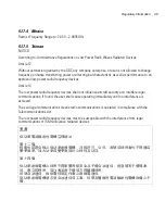
Page 43: ...400 2483 5MHz or 5725 5825MHz the following expressions should be displayed 1 This radio equipment can be interfered with during operation 2 This radio equipment cannot provide a service relevant to human life safety as it can be crossed through the user manual etc 在 5 25 5 35 赫頻帶內操作之無線資訊傳輸設備 限於室內使用 당해 무선설비는 운용 중 전파혼신 가능성이 있음 당해 무선설비 는전파혼 신 가능성이 있으므로 인명안전과 관련된 서비스는 할 수 없습니다 ...

Page 44: ...tion Serial number of the unit Model number or product name Software type and version number Motorola responds to calls by email telephone or fax within the time limits set forth in support agreements If you purchased your Enterprise Mobility business product from a Motorola business partner contact that business partner for support 6 1 Customer Support Web Sites Motorola s Support Central Web sit...

Page 45: ...AP 6511 Access Point Installation Guide 42 ...

Page 46: ...MOTOROLA INC 1303 E ALGONQUIN ROAD SCHAUMBURG IL 60196 http www motorola com 72 XXXXXX 01 Revision A November 2010 ...

Reviews: