background image

Regulatory Information

23

Consult the dealer or an experienced radio/TV technician for help

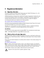
Radio Transmitters (Part 15)

This device complies with Part 15 of the FCC Rules. Operation is subject to the following two 
conditions: (1) this device may not cause harmful interference, and (2) this device must accept any 
interference received, including interference that may cause undesired operation.

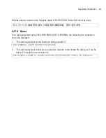
Restricted Band 5.60 – 5.65 GHz 

4.10    Radio Frequency Interference Requirements – Canada 

This Class B digital apparatus complies with Canadian ICES-003.

Cet appareil numérique de la classe B est conforme à la norme NMB-003 du Canada.

4.10.1    Radio Transmitters

For RLAN Devices:

The use of 5 GHz RLAN’s, for use in Canada, have the following restrictions:

Restricted Band 5.60 – 5.65 GHz 

This device complies with RSS 210 of Industry & Science Canada. Operation is subject to the 
following two conditions: (1) this device may not cause harmful interference and (2) this device must 
accept any interference received, including interference that may cause undesired operation.

Label Marking: The Term "IC:" before the radio certification only signifies that Industry Canada 
technical specifications were met.

Summary of Contents for AP-0650-60010 Series

Page 1: ...AP 650 Series Thin Access Point Installation Guide M ...

Page 2: ...ogo are registered in the US Patent Trademark Office Sym bol is a registered trademark of Symbol Technologies Inc All other product or service names are the property of their respective owners Motorola Inc 2010 All rights reserved ...

Page 3: ... Wall Mount Instructions 5 2 4 1 Wall Mount Hardware 6 2 4 2 Wall Mount Procedure 7 2 5 Integrated Antenna Model Suspended Ceiling T Bar Mount Instructions 9 2 5 1 Suspended Ceiling Mount Procedure 9 2 6 External Antenna Model Wall Mount Instructions 10 2 6 1 Wall Mount Hardware 10 2 6 2 Wall Mount Procedure 11 2 7 External Antenna Model Suspended Ceiling Tile Plenum Mount Instructions 12 2 7 1 Su...

Page 4: ...0 4 3 1 Warnings for the use of Wireless Devices 20 4 3 2 Potentially Hazardous Atmospheres Fixed Installations 20 4 3 3 Safety in Hospitals 21 4 4 RF Exposure Guidelines 21 4 4 1 Safety Information 21 4 5 International 21 4 6 EU 22 4 7 US and Canada 22 4 8 Power Supply 22 4 9 Radio Frequency Interference Requirements FCC 22 4 10 Radio Frequency Interference Requirements Canada 23 4 10 1 Radio Tra...

Page 5: ...7 4 17 2 Brazil 27 4 17 3 Chile 27 4 17 4 Mexico 28 4 17 5 Taiwan 28 4 17 6 Korea 29 5 Motorola s Enterprise Mobility Support Center 30 5 1 Customer Support Web Sites 30 5 2 Manuals 30 6 AP 650 Series ROHS Compliance 31 ...

Page 6: ...s no additional power supply required An 802 3af Ethernet switch or power injector is required 1 1 Document Conventions The following graphical alerts are used in this document to indicate notable situations 1 2 Warnings Read all installation instructions and site survey reports and verify correct equipment installation before connecting the AP 650 Thin Access Point Remove jewelry and watches befo...

Page 7: ...ble distances for optimal signal transmission 1 4 AP 650 Package Contents The AP 650 model Thin Access Point comes in four configurations two Integrated Antenna models and two External Antenna models The contents of the package differ between the Integrated Antenna model and the External Antenna model 1 4 1 External Antenna Model Package Contents AP 650 Thin Access Point with external antenna conn...

Page 8: ...t power from an external source The AP 650 Thin Access Point comes in both single and dual radio versions both supporting 802 11a b g n The Thin Access Point contains runtime firmware which enables the unit to boot after either a power up or a watchdog reset The runtime firmware on the Thin Access Point and the firmware downloaded from the switch can be updated via the Ethernet interface from the ...

Page 9: ...ion for the AP 650 Thin Access Point Part Number Description AP 0650 60010 XX 802 11a b g n single radio integrated antenna configuration AP 0650 66030 XX 802 11a b g n dual radio integrated antenna configuration AP 0650 60020 XX 802 11a b g n single radio external antenna configuration AP 0650 66040 XX 802 11a b g n dual radio external antenna configuration NOTE In the above part numbers XX repre...

Page 10: ...hting Users might find an area lit from far away to be not bright enough An area lit sharply might minimize coverage and create dark areas Uniform antenna placement in an area like even placement of a light bulb provides even efficient coverage Place the access point using the following guidelines Install the access point at an ideal height of 10 feet from the ground Orient the access point antenn...

Page 11: ...ips pan head self tapping screws Two wall anchors Security cable optional NOTE In the event that the original mounting screws are lost the following screws can be used instead ANSI Standard 6 18 X 0 875in Type A or AB Self Tapping Screw or ANSI Standard Metric M3 5 X 0 6 X 20mm Type D Self Tapping Screw ...

Page 12: ...the case as guides move the edge to the midline of the mounting area and mark points on the midline for the screws CAUTION To ensure proper operation of the AP 650 Thin Access Point ensure that the thin access point is mounted in the correct orientation as shown above Integrated Antenna Wall Mount Correct Orientation Incorrect Orientation ...

Page 13: ...the Ethernet cable to the unit and to a switch with an 802 3af compatible power source 6 Place the middle of each of the case s mount slots over the screw heads 7 Slide the case down along the mounting surface to hang the mount slots on the screw heads 8 Verify the unit has power by observing that the LEDs are lit or flashing NOTE When pre drilling a hole the recommended hole size is 2 8mm 0 11in ...

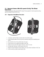
Page 14: ...security cable to the unit s lock port 2 Plug the Ethernet cable into the unit and to a switch with an 802 3af compatible power source 3 Face the bottom of the T bar with the back of the case 4 Orient the case by its length and the length of the T bar 5 Rotate the case in place 45 degrees clockwise or about 10 o clock 6 Push the back of the case onto the bottom of the T bar 7 Rotate the case 45 de...

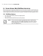
Page 15: ...r cement wall surface using the provided wall anchors when necessary The illustration shows a lengthwise mount 2 6 1 Wall Mount Hardware Two wide shoulder Phillips pan head self tapping screws Two wall anchors Safety wire recommended and security cable optional NOTE In the event that the original mounting screws are lost the following screws can be used instead ANSI Standard 6 18 X 0 875in Type A ...

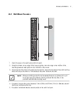
Page 16: ...insert an anchor screw into the anchor the wall mounting screw and stop when there is 1mm between the screw head and the wall 4 If required loop a safety wire between 1 5mm 06in and 2 5mm 10in in diameter around the tie post and secure the loop 5 If required install and attach a security cable to the unit s lock port NOTE When pre drilling a hole the recommended hole size is 2 8mm 0 11in if the sc...

Page 17: ...ent requires installation of the provided light pipe for viewing the status lights of the unit 2 7 1 Suspended Ceiling Mount Hardware Light pipe Badge for light pipe Safety wire recommended and security cable optional NOTE Notes or warnings about suspended ceiling mounts apply to all installations where the unit is placed on suspended ceiling tile The case has a safety wire tie point for a standar...

Page 18: ...pipe If necessary use a drill to make a hole in the tile 6 Attach appropriate antennas to the connectors 7 Snap the clips of the light pipe into the bottom of the case 8 Fit the light pipe into hole in the tile from its unfinished side 9 Attach any safety wire to the safety wire tie point or security cable to the unit s lock port 10 Bring the tile into the ceiling space 11 Plug the Ethernet cable ...

Page 19: ...appropriate single band antenna The 2 4 GHz antenna suite includes the following models The 5 GHz antenna suite includes the following models For up to date information on supported antennas and antenna specifications please see the Motorola Antenna Specification Guide available on the Motorola website Part Number Antenna Type ML 2499 HPA3 01R Omni Directional Antenna ML 2499 SD3 01R Patch Antenna...

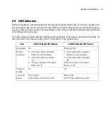
Page 20: ...itions transmission and network activity for the 5 GHz 802 11a n amber radio or the 2 4 GHz 802 11b g n green radio Task 5 GHz Activity LED Amber 2 4 GHz Activity LED Green Unadopted Off Blinking at 5Hz Normal Operation If this radio band is enabled Blink at 5 second interval If this radio band is disabled Off If there is activity on this band Blink at a 1Hz If this radio band is enabled Blink at ...

Page 21: ...hysical characteristics Operating Current Voltage 180ma 270ma 48VDC Dimensions 8 50 in Depth x 5 5 in Width x 1 5 in Height 21 59 cm Depth x 13 97 cm Width x 3 81 cm Height Housing Metal Weight 2 5 lbs 1 13 kg Operating Temperature 32 F to 122 F 0 C to 50 C Storage Temperature 40 F to 158 F 40 C to 70 C Operating Humidity 5 to 95 Relative Humidity non condensing Storage Humidity 85 Relative Humidi...

Page 22: ...rating Current Voltage 180ma 270ma 48VDC Dimensions 9 50 in Depth x 7 5 in Width x 1 9 in Height 24 13 cm Depth x 19 05 cm Width x 4 83 cm Height Housing Plastic Weight 2 0 lbs 0 91 kg Operating Temperature 32 F to 122 F 0 C to 50 C Storage Temperature 40 F to 158 F 40 C to 70 C Operating Humidity 5 to 95 Relative Humidity non condensing Storage Humidity 85 Relative Humidity non condensing Operati...

Page 23: ... 24 36 48 and 54Mbps 802 11n MCS 0 15 up to 300Mbps Wireless Medium Direct Sequence Spread Spectrum DSSS Orthogonal Frequency Division Multiplexing OFDM Spatial multiplexing MIMO Network Standards 802 11a 802 11b 802 11g 802 3 802 11n Draft 2 0 Maximum Available Transmit Power Maximum available conducted transmit power per chain 2 4 GHz 21dBm Maximum available conducted transmit power all chains 2...

Page 24: ...uthorized antennas modifications or attachments could cause damage and may violate regulations Radio Modules This Access Point contains approved radio module s MB82 These module s are identified below MB82 a DFS Master WLAN 802 11 abgn MIMO 2x3 radio module 4 2 Wireless Device Country Approvals Regulatory markings subject to certification are applied to the device signifying the radio s is are app...

Page 25: ...has been disabled in the US version of the Access Point The available channels for 802 11 b g operation in the US are Channels 1 to 11 The range of channels is limited by firmware 2 4 GHz Only The available channels for 802 11 b g operation in the US are Channels 1 to 11 The range of channels is limited by firmware Enclosure Labels The FCC requires that the FCC ID label be place on the outside of ...

Page 26: ...urned ON Should not carry the device in a breast pocket Should use the ear furthest from the pacemaker to minimize the potential for interference If you have any reason to suspect that interference is taking place turn OFF your device Other Medical Devices Please consult your physician or the manufacturer of the medical device to determine if the operation of your wireless product may interfere wi...

Page 27: ...s powered from a 802 3af compliant power source which is UL approved and certified by the appropriate agencies 4 9 Radio Frequency Interference Requirements FCC This equipment has been tested and found to comply with the limits for a Class B digital device pursuant to Part 15 of the FCC rules These limits are designed to provide reasonable protection against harmful interference in a residential i...

Page 28: ...B digital apparatus complies with Canadian ICES 003 Cet appareil numérique de la classe B est conforme à la norme NMB 003 du Canada 4 10 1 Radio Transmitters For RLAN Devices The use of 5 GHz RLAN s for use in Canada have the following restrictions Restricted Band 5 60 5 65 GHz This device complies with RSS 210 of Industry Science Canada Operation is subject to the following two conditions 1 this ...

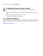
Page 29: ...wer of 100 mW EIRP in the frequency range 2 400 2 4835 GHz France outside usage is restricted to 2 4 2 454 GHz Italy requires a user license for outside usage 4 12 Statement of Compliance Motorola Symbol hereby declares that this device is in compliance with the essential requirements and other relevant provisions of Directive 1999 5 EC A Declaration of Conformity may be obtained from http www2 sy...

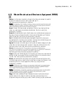
Page 30: ...i http www symbol com environmental_compliance Español Para clientes en la Unión Europea todos los productos deberán entregarse a Symbol al final de su ciclo de vida para que sean reciclados Si desea más información sobre cómo devolver un producto visite http www symbol com environmental_compliance Français Clients de l Union Européenne Tous les produits en fin de cycle de vie doivent être retourn...

Page 31: ...oor klanten in de EU alle producten dienen aan het einde van hun levensduur naar Symbol te worden teruggezonden voor recycling Raadpleeg http www symbol com environmental_compliance voor meer informatie over het terugzenden van producten Português Para clientes da UE todos os produtos no fim de vida devem ser devolvidos à Symbol para reciclagem Para obter informações sobre como devolver o produto ...

Page 32: ...marca de certificação se aplica ao Transceptor modelo AP 650 Este equipamento opera em caráter secundário isto é não tem direito a proteção contra interferência prejudicial mesmo de estações do mesmo tipo e não pode causar interferência a sistemas operando em caráter primário Para maiores informações sobre ANATEL consulte o site http www anatel gov br 4 17 3 Chile Este equipo cumple con la Resoluc...

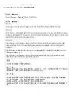
Page 33: ...rticle 14 The low power radio frequency devices shall not influence aircraft security and interfere legal communications If found the user shall cease operating immediately until no interference is achieved The said legal communications means radio communications is operated in compliance with the Telecommunications Act The low power radio frequency devices must be susceptible with the interferenc...

Page 34: ...5MHz or 5725 5825MHz the following two expression should be displayed 1 This radio equipment can be interfered during operation 2 This radio equipment cannot provide a service relevant to the human life safety as it can be crossed through the user manual etc 在 5 25 5 35 赫頻帶內操作之無線資訊傳輸設備 限於室內使用 당해 무선설비는 운용 중 전파혼신 가능성이 있음 당해 무선설비 는전파혼 신 가능성이 있으므로 인명안전과 관련된 서비스는 할 수 없습니다 ...

Page 35: ...t please provide the following information Serial number of the unit Model number or product name Software type and version number Motorola responds to calls by email or telephone within the time limits set forth in support agreements If you purchased your Enterprise Mobility business product from a Motorola business partner contact that business partner for support 5 1 Customer Support Web Sites ...

Page 36: ...中可能会也可能不会含有所有所列的部件 This table was created to comply with China RoHS requirements for Motorola s AP 650 model access points 部件名称 Parts 有毒有害物质或元素 铅 Pb 汞 Hg 镉 Cd 六价铬 Cr6 多溴联 苯 PBB 多溴二苯 醚 PBDE 金属部件 Metal Parts X O O O O O 电路模块 Circuit Modules X O O O O O 电缆及电缆组件 Cables and Cable Assemblies O O O O O O 塑料和聚合物部件 Plastic and Polymeric Parts O O O O O O 光学和光学组件 Optics and Optical Components O O O O O O 电池...

Page 37: ...AP 650 Series Thin Access Point Installation Guide 32 ...

Page 38: ...MOTOROLA INC 1303 E ALGONQUIN ROAD SCHAUMBURG IL 60196 http www motorola com 72E 131207 01 Revision D September 2010 ...

Reviews: