background image

Introduction

RF-Conductor! Controller NIU Remote Configuration

1-2

6880494G55-O

May 1998

About this Manual

This manual describes the infrastructure command messages (ICMs) of the RF-Conductor!
controller used in the WMS-Data system. It is intended for network administrators and site
operators responsible for remotely downloading general purpose commands carried by the
SuperStream transport protocol to internal and external Network Interface Units (NIUs).

The organization of the manual follows the structure of the Infrastructure Commands sub-
menus of the WMS-Data Operator Console software (see Figure 1-1), and is divided in
sections, one for each main menu item:

Chapter 1, "Introduction", provides a description of the manual’s purpose and contents.
Also included are the basic instructions on how to use the WMS-Data operator console
interface software.

Chapter 2, "Infrastructure Commands Overview", provides an overview of the
Infrastructure Commands Group menu.

Chapter 3, "Alignment Commands", describes adding and deleting a maintenance group,
changing alignment type, setting GPS offset and link path delay, and recalculating GPS.

Chapter 4, "SuperStream Commands", provides procedures for changing specific
parameters that uniquely identify each transmitter.

Chapter 5, "Diagnostic Commands", details the various diagnostic commands available
to the administrator: setting auxiliary outputs, resetting the dial modem, changing a
password, setting date and time, resetting NIU alarms, resetting a transmitter, setting bit
error rate (BER), setting Failsafe Timeout, and disabling paging.

Chapter 6, "Software Linkload Commands", provides procedures for downloading
software to the transmitters.

Chapter 7, "Site Encoding Commands", provides procedures for changing transmitter
color codes and channels, setting polarity for FLEX and POCSAG, and setting station ID
and mode.

Appendix A, "Configuring the Esprit 5055 Video Display Terminal" describes the
configuration of the Video Display Terminal (VDT) that is used as the RF-C!™ Controller
Operator Console.

Summary of Contents for 3200

Page 1: ...RF Conductor Controller NIU Remote Configuration Issue Date May 1998 6880494G55 O Series Wireless Messaging System System Version WMS Data Software Version 1 3 and WMS Two Way 3 0 Models 3200 and 3210 ...

Page 2: ......

Page 3: ...RF Conductor Controller NIU Remote Configuration Issue Date May 1998 6880494G55 O Series Wireless Messaging System System Version WMS Data Software Version 1 3 ...

Page 4: ......

Page 5: ...Motorola convey any license under its patents or right of others Refer questions concerning the contents of this manual or requests for related circuit board information to the following location Motorola Inc Paging Systems Group Multimedia Publications Department 5401 North Beach St MS E230 A Fort Worth TX 76137 2794 or telephone 817 245 4222 To access on line electronic information BBS for servi...

Page 6: ... 817 245 4663 facsimile 817 245 2141 Service Training Motorola through its Advanced Messaging Technical Training Group in Fort Worth Texas offers courses on communicators messaging switches transmitters and receivers These courses are taught on the site or at a customer s location Students learn to install configure and maintain Motorola messaging systems The classrooms at Motorola are equipped to...

Page 7: ...ter software contained in the Motorola products described in this manual cannot be copied or reproduced in any manner without the express written permission of Motorola Furthermore the purchase of Motorola products does not grant either directly or by implication estoppel or otherwise any license under the copyrights patents or patent applications of Motorola except for the normal nonexclusive roy...

Page 8: ...l code requirements safe working practices and good judgement must be used by personnel Heed Admonitions Adhere to all warnings on the equipment and in the operating instructions Follow all operating and use instructions Two safety admonitions are used in this instruction manual to indicate Equipment damage Personal injury or injury that may result in death Mounting Mount the equipment only as rec...

Page 9: ...mmerse the equipment in any type of liquid including water Do not use liquid cleaners or aerosol cleaners Dirt or other foreign matter should not be allowed to accumulate in the interior of the enclosure Damage Requiring Service Do not attempt to perform service functions that are not described in the operating instructions All other servicing should be referred to qualified service personnel Tele...

Page 10: ...Foreword RF Conductor Controller NIU Remote Configuration viii 6880494G55 O May 1998 ...

Page 11: ...e date of shipment of the PSG infrastructure equipment 5 The term of Warranty for all PSG infrastructure equipment except for AlphaMate 250 paging entry terminal products is one 1 year parts and labor The term of Warranty for AlphaMate 250 paging entry terminals is one 1 year parts and 120 days labor in Motorola PSG authorized service centers In field labor for warranty claims excluding AlphaMate ...

Page 12: ...ion with incompatible equipment unless such use was with or under Motorola s prior written consent f Cosmetic damages g Damages caused by external electrical stress h Lightning i Accidental damage j Negligence neglect mishandling abuse or misuse k Force Majeure and l Damage caused by Shipper s Return of Equipment 8 If an item of PSG infrastructure equipment malfunctions or fails in normal use with...

Page 13: ...fects in material and workmanship for the remainder of the original Warranty or for 90 days from the date of repair or replacement whichever is longer All other terms of this Warranty shall apply to such repairs or replacements Advance Replacements 9 During the Warranty Period a At the Customer s request and for the Customer s convenience Motorola may supply the Customer with Advance Replacement P...

Page 14: ... Motorola such as batteries and satellite dish LNBs b Peripheral equipment such as printers modems data loggers video display terminals and lightning and surge protectors and c Equipment which is not listed in Motorola s Price Book Force Majeure 13 Motorola shall not be responsible for failure to discharge its obligations under this Warranty due to delays by suppliers material shortages strikes lo...

Page 15: ... Limitation of Liability 16 IN NO EVENT SHALL MOTOROLA BE LIABLE FOR ANY INDIRECT INCIDENTAL SPECIAL OR CONSEQUENTIAL DAMAGES ARISING OUT OF THIS WARRANTY EVEN IF MOTOROLA HAS BEEN ADVISED OF THE POSSIBILITY THEREOF INCLUDING WITHOUT LIMITATION LOST PROFITS AND REVENUES FAILURE TO REALIZE EXPECTED SAVINGS LOST DATA OR ANY CLAIMS AGAINST THE CUSTOMER BY A THIRD PARTY ...

Page 16: ...Warranty xiv Revised July 1997 ...

Page 17: ...arameters 2 4 Accessing the Infrastructure Command Groups Menu Administrator Level 2 6 Accessing the Infrastructure Command Groups Menu Site Operator Level 2 10 Alignment Commands 3 1 Adding a Maintenance Group 3 2 Deleting a Maintenance Group 3 4 Changing Alignment Type 3 6 Setting GPS Offset 3 9 Setting Link Path Delay 3 11 Recalculating GPS 3 13 SuperStream Commands 4 1 Introduction 4 2 Changin...

Page 18: ...r 5 17 Setting Bit Error Rate BER Limit 5 18 Setting Failsafe Timeout 5 20 Disabling Paging 5 23 Software Linkload Commands 6 1 Installing an NIU SCM Release from Tape 6 2 Deleting an Installed NIU SCM Release 6 4 Linkloading an Installed NIU SCM Release 6 6 Sending Bank Switch by Version Command 6 10 Aborting a Linkload to a Station Control Module SCM Flash 6 13 Site Encoding Commands 7 1 Changin...

Page 19: ...RF Conductor Controller NIU Remote Configuration Contents May 1998 6880494G55 O xvii Configuring the Esprit 5055 Video Display Terminal A 1 Overview A 2 Configuring the Esprit 5055 VDT A 3 ...

Page 20: ...Contents RF Conductor Controller NIU Remote Configuration xviii 6880494G55 O May 1998 ...

Page 21: ...astructure Commands Groups Menu Site Operator Level 2 13 Figure 3 1 Alignment Menu Add Maintenance Group 3 2 Figure 3 2 Add Maintenance Group Menu 3 3 Figure 3 3 Alignment Menu Delete Maintenance Group 3 4 Figure 3 4 Delete Maintenance Group Menu 3 5 Figure 3 5 Alignment Menu Change Alignment Type 3 6 Figure 3 6 Select Alignment Type Menu 3 7 Figure 3 7 Change Alignment Type GPS Sync Options Menu ...

Page 22: ...Alarms Log Stats 5 14 Figure 5 14 Diagnostics Screen Reset NIU Log 5 15 Figure 5 15 Diagnostics Screen Reset NIU Stats 5 16 Figure 5 16 Diagnostics Screen Reset Transmitter 5 17 Figure 5 17 Diagnostics Screen Set BER Limit 5 18 Figure 5 18 Set BER Limit Screen 5 19 Figure 5 19 Diagnostics Screen Set Failsafe Timeout 5 20 Figure 5 20 Select Failsafe Timeout Screen 5 21 Figure 5 21 Change Failsafe T...

Page 23: ...ucture Command Groups Set Transmitter Channels 7 5 Figure 7 5 Select Channel Options Screen 7 6 Figure 7 6 Set Transmitter Channels Screen 7 7 Figure 7 7 Re Configure Channels Screen 7 8 Figure 7 8 Infrastructure Command Groups Set FLEX ReFLEX Polarity 7 9 Figure 7 9 Select FLEX ReFLEX Data Polarity Screen 7 10 Figure 7 10 Infrastructure Command Groups Set POCSAG Polarity 7 11 Figure 7 11 Select P...

Page 24: ...Figures RF Conductor Controller NIU Remote Configuration xxii 6880494G55 O May 1998 ...

Page 25: ...n May 1998 6880494G55 O xxiii Tables Table 1 1 Keyboard Conventions Used in This Manual 1 3 Table 1 2 Navigation Conventions 1 10 Table 2 1 Infrastructure Command Group Menu Options 2 4 Table A 1 Esprit Navigation Keys A 3 Table A 2 Esprit Setup A 4 ...

Page 26: ...Tables RF Conductor Controller NIU Remote Configuration xxiv 6880494G55 O May 1998 ...

Page 27: ...e administration of the WMS Data operator console for the RF Conductor RF C controller and contains the following topics About this Manual 1 2 Keyboard Conventions 1 3 Related Publications 1 4 Basic RF C Controller Instructions 1 5 Setting up Passwords 1 5 Logging into the System 1 6 Screen Areas 1 8 Navigating the System 1 9 ...

Page 28: ...overview of the Infrastructure Commands Group menu Chapter 3 Alignment Commands describes adding and deleting a maintenance group changing alignment type setting GPS offset and link path delay and recalculating GPS Chapter 4 SuperStream Commands provides procedures for changing specific parameters that uniquely identify each transmitter Chapter 5 Diagnostic Commands details the various diagnostic ...

Page 29: ...se procedures use Enter to represent the various labeling Unless otherwise noted the sequence is Item Enter Also Control or Ctrl may indicate the control key These procedures use Ctrl Variables Variables that you must type into the system are set inside vertical brackets However you do not type the brackets Examples Latitude 177 12 77 34 System output System responses to commands appear as Helveti...

Page 30: ... related to this topic are RF Conductor Controller Installation 6880494G53 RF Conductor Controller Administration 6880494G54 External NIU Transmitter Controller Installation and Operation 6880497G10 Internal NIU Transmitter Controller Installation and Operation 6880497G15 Nucleus Paging Station Installation and Operation 6881002F05 ...

Page 31: ...ystem Administration manual RF Conductor Operation and Software Installation 6880494G54 for information on setting your access level Setting up Passwords The first time RF C controller user either as an administrator viewer or site operator is prompted to set up a password Once the initial password is set up for each type of user the password prompt does not display After logging in the administra...

Page 32: ...80494G55 O May 1998 Logging into the System To begin an administrator level session 1 Type admin The system prompts Enter password 2 Type your password The WMS Data Operator Console displays see Figure 1 1 Figure 1 1 WMS Data Operator Console Menu Administrator Options ...

Page 33: ...he system prompts Enter password 2 Type your password The WMS Data Operator Console displays see Figure 1 1 To begin a site operator level session 1 Type siteoper The system prompts Enter password 2 Type your password The WMS Data Operator Console displays see Figure 1 2 Figure 1 2 WMS Data Operator Console Menu Site Operator Options ...

Page 34: ... messages pertaining to the information in the active area Events and alarms bar The events and alarms bar contains system messages which are logged by the RF C controller The event display can be configured by the administrative level user using the Map Actions to Events screen Date and time bar The date and time bar displays the current RF C controller date and the time In addition the system di...

Page 35: ...bal options Other commands can only be executed on specific screens These commands are window options To assist the user when invalid data is input the system responds with the valid options in the message bar Navigating the System Every screen uses the same navigation logic for moving the cursor typing information and sending data to the RF C controller see Table 1 2 Current selection indicator A...

Page 36: ...r up arrow left left arrow right right arrow Select item from a menu at cursor position indicated by Return Move forward in the window Ctrl F forward Move backwards in the window Ctrl B backward Return to the previous window displayed Ctrl P previous View global options Ctrl G global View the window options which are the control sequences used in the current screen Ctrl W window Send data or comma...

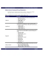
Page 37: ...s chapter discusses the intrastructure commands windows and includes the following topics Infrastructure Command Messages Overview 2 2 Infrastructure Command Group Parameters 2 4 Accessing the Infrastructure Command Groups Menu Administrator Level 2 6 Accessing the Infrastructure Command Groups Menu Site Operator Level 2 10 ...

Page 38: ...itters in a SuperStream system All transmitters in a zone A single transmitter The relationship of streams SuperStream systems zones and transmitters is shown in Figure 2 1 The following examples show how the command structure can be used to target various transmitter groups shown in the figure To send command messages to all the transmitters on a particular link select All transmitters in a strea...

Page 39: ...494G55 O 2 3 Figure 2 1 Relationship of Streams SuperStream Systems Zones and Transmitters SuperStream System 1 SuperStream System 2 SuperStream System 3 Zone 1 Zone 1 Zone 2 Transmitter 1 Transmitter 2 Transmitter 9 Transmitter 10 Trans 3 Trans 4 Trans 5 Trans 6 Trans 7 Trans 8 Stream 455SRH 01 ...

Page 40: ... is used to change the specific parameters that uniquely identify each transmitter It has these options Change Zone Map Change Device ID Change Maintenance ID Change System ID Change Link Parameters Diagnostic This command group provides diagnostic commands between the RF C controller system and the transmitters It includes the following menu options Set Auxiliary Outputs Reset Dial Modem Enable M...

Page 41: ...s an option for aborting the SCM linkload Site Encoding This command group provides site encoding commands Change Color Code Set Transmitter Channels Set FLEX ReFLEX Polarity Set POCSAG Polarity Set Maintenance Polarity Set Station ID Set Station ID Mode Table 2 1 Infrastructure Command Group Menu Options Sheet 2 of 2 Menu Option Description ...

Page 42: ...te To move position the cursor on the screen use the tab or down arrow to move down backspace or up arrow to move up left arrow to move to the left and the right arrow to move to the right 1 Display the WMS Data Operator Console Menu see Figure 2 2 2 Use the tab to position the cursor to the left of the listing Infrastructure Commands and press Return Figure 2 2 Infrastructure Commands Menu Admini...

Page 43: ...and press Return Figure 2 3 Infrastructure Command Group Select a Distribution Link ID Menu The Select Destination menu displays see Figure 2 4 4 Use the tab to position the cursor to the left of the destination types and press Return Select the type of destination from the following options a All Transmitters in a Stream displays the Infrastructure Commands Group menu b All Transmitters in a Supe...

Page 44: ... to enter SuperStream System ID and the zone ID before displaying the Infrastructure Commands Group menu d To a Single Transmitter prompts you to enter transmitter ID before displaying the Infrastructure Commands Group menu The Infrastructure Commands Groups menu appears see Figure 2 5 Figure 2 4 Select Destination Menu for Infrastructure Commands ...

Page 45: ...mote Configuration Infrastructure Commands Overview May 1998 6880494G55 O 2 9 Figure 2 5 Infrastructure Commands Groups Menu Administrator Level 5 Make the desired menu selection 6 To return to a previous menu or screen press Ctrl p ...

Page 46: ...te To move position the cursor on the screen use the tab or down arrow to move down backspace or up arrow to move up left arrow to move to the left and the right arrow to move to the right 1 Display the WMS Data Operator Console Menu see Figure 2 6 2 Use the tab to position the cursor to the left of the listing Infrastructure Commands and press Return Figure 2 6 Infrastructure Commands Menu Site O...

Page 47: ... and press Return Figure 2 7 Infrastructure Command Group Select a Distribution Link ID Menu The Select Destination menu displays see Figure 2 8 4 Use the tab to position the cursor to the left of the destination types and press Return Select the type of destination from the following options a All Transmitters in a Stream displays the Infrastructure Commands Group menu b All Transmitters in a Sup...

Page 48: ... to enter SuperStream System ID and the zone ID before displaying the Infrastructure Commands Group menu d To a Single Transmitter prompts you to enter transmitter ID before displaying the Infrastructure Commands Group menu Figure 2 8 Select Destination Menu for Infrastructure Commands 5 The Infrastructure Commands Groups menu appears see Figure 2 9 ...

Page 49: ...ote Configuration Infrastructure Commands Overview May 1998 6880494G55 O 2 13 Figure 2 9 Infrastructure Commands Groups Menu Site Operator Level 6 Make the desired menu selection 7 To return to a previous menu or screen press Ctrl p ...

Page 50: ...Infrastructure Commands Overview RF Conductor Controller NIU Remote Configuration 2 14 6880494G55 O May 1998 ...

Page 51: ...O 3 1 Alignment Commands 3 This chapter discusses the Alignment commands and provides procedures for the following Adding a Maintenance Group 3 2 Deleting a Maintenance Group 3 4 Changing Alignment Type 3 6 Setting GPS Offset 3 9 Setting Link Path Delay 3 11 Recalculating GPS 3 13 ...

Page 52: ...ion the cursor on the screen use the tab or down arrow to move down backspace or up arrow to move up left arrow to move to the left and the right arrow to move to the right 1 From the Alignment menu use the tab to position the cursor to the left of the listing Add Maintenance Group and press Return see Figure 3 1 Figure 3 1 Alignment Menu Add Maintenance Group The Add Maintenance Group screen appe...

Page 53: ...nge of Maintenance IDs is 0 63 If a new Maintenance ID matches an existing Maintenance ID in the monitor receiver it is overwritten 3 Enter the Air Delay and press Return Valid values are 0 50000 in microseconds 4 Enter the Device ID that has this maintenance ID programmed Valid values are 1 8191 5 Press Ctrl e to execute the command 6 To return to a previous menu or screen press Ctrl p ...

Page 54: ...command is used to delete a maintenance ID of a monitor receiver controller 1 From the Alignment menu use the tab to position the cursor to the left of the listing Delete Maintenance Group and press Return see Figure 3 3 Figure 3 3 Alignment Menu Delete Maintenance Group The Delete Maintenance Group screen appears see Figure 3 4 ...

Page 55: ...ration Alignment Commands May 1998 6880494G55 O 3 5 Figure 3 4 Delete Maintenance Group Menu 2 Enter the Maintenance ID to delete and press Return The valid range of Maintenance IDs is 0 63 3 To return to a previous menu or screen press Ctrl p ...

Page 56: ...ires a link with a constant propagation delay to establish system synchronization The GPS synchronization method uses timing information from the global positioning system satellites for system synchronization The options field defines whether the GPS synchronization method uses GPS with fallback enabled or disabled 1 From the Alignment menu use the tab to position the cursor to the left of the li...

Page 57: ...Sync options screen appears see Figure 3 7 The GPS fallback is disabled by default 3 In the Enable Fallback field press ctrl t to toggle between n for no and y for yes While using GPS synchronization method it is recommended to enable fallback 4 Press Ctrl e to execute the command CAUTION It is possible to lose pages while going from one alignment type to the other Consider suspending the coverage...

Page 58: ...To return to the previous menu or screen press Ctrl p 6 To select Direct Sync alignment position the cursor to the left of the listing Direct Sync and press Return to execute the command There are no parameter options for Direct Sync alignment Figure 3 7 Change Alignment Type GPS Sync Options Menu ...

Page 59: ...opriate results 1 From the Alignment menu use the tab to position the cursor to the left of the listing Set GPS Offset and press Return see Figure 3 8 Figure 3 8 Alignment Menu Set GPS Offset 2 The Select Sign screen appears Position the cursor to select Positive or Negative and press Return 3 The Select Offset screen appears Position the cursor to select Absolute or Relative and press Return Abso...

Page 60: ...PS Offset and press ctrl e to execute the command The valid range is 0 450000 in microseconds Note Use the delay values from the maintenance data only Do not vary the value by large numbers unless reported by the maintenance report Suspend the system to avoid losing pages 6 To return to the previous menu or screen press Ctrl p Figure 3 9 Set GPS Offset Screen ...

Page 61: ...nce command to ensure that the offset value entered provides the appropriate results 1 From the Alignment menu use the tab to position the cursor to the left of the listing Setting Link Path Delay and press Return see Figure 3 10 Figure 3 10 Alignment Menu Setting Link Path Delay 2 The Select Sign screen appears Position the cursor to select Positive or Negative and press Return 3 The Select Delay...

Page 62: ...xecute the command The valid range is 0 400000 in microseconds Note Use the delay values from the maintenance data only Do not vary the value by large numbers unless reported by the maintenance report Suspend the system to keep from losing pages 6 To return to the previous menu or screen press Ctrl p Figure 3 11 Set Link Path Delay Screen ...

Page 63: ...g an RF C NIU installation and is applicable only to the NIU if it is a GPS master NIU Note Before executing this command suspend the system to keep from losing pages 1 From the Alignment menu use the tab to position the cursor to the left of the listing Recalculate GPS and press Return to execute the command see Figure 3 12 Figure 3 12 Alignment Menu Recalculate GPS The Infrastructure Commands Gr...

Page 64: ...Alignment Commands RF Conductor Controller NIU Remote Configuration 3 14 6880494G55 O May 1998 ...
Page 65: ...494G55 O 4 1 SuperStream Commands 4 This chapter discusses the SuperStream commands and provides procedures for the following Introduction 4 2 Changing a Zone Map 4 3 Changing a Device ID 4 5 Changing Maintenance IDs 4 7 Changing System IDs 4 9 Changing Link Parameters 4 12 ...

Page 66: ... uniquely identify each transmitter 1 To access SuperStream commands From the Infrastructure Command Groups menu use the tab to position the cursor to the left of the listing SuperStream and press Return see Figure 4 1 2 The SuperStream menu appears All procedures in this chapter are referenced from the SuperStream menu Figure 4 1 Selecting SuperStream from the Infrastructure Command Groups Menu ...

Page 67: ...s for multicasting of messages for example for page data distribution to multiple transmitters 1 From the SuperStream menu use the tab to position the cursor to the left of the listing Change Zone Map and press Return see Figure 4 2 Figure 4 2 SuperStream Menu Change Zone Map The Select Zone Options screen appears 2 Position the cursor to add or delete a zone and press Return 3 The Change Zone Map...

Page 68: ...Commands RF Conductor Controller NIU Remote Configuration 4 4 6880494G55 O May 1998 Figure 4 3 Select Zone Options Screen 5 Press Ctrl e to execute the command 6 To return to a previous menu or screen press Ctrl p ...

Page 69: ... a single transmitter 1 From the SuperStream menu use the tab to position the cursor to the left of the listing Change Device ID and press Return see Figure 4 4 Figure 4 4 SuperStream Menu Change Device ID The Change Device ID screen appears see Figure 4 5 2 Enter the Device ID and press Return Valid values are 1 8191 The Infrastructure Commands Group menu appears with a message Command request ac...

Page 70: ...SuperStream Commands RF Conductor Controller NIU Remote Configuration 4 6 6880494G55 O May 1998 Figure 4 5 Change Device ID Screen ...

Page 71: ...ance cycle starts with ID 0 and ends with ID 63 depending on the number of maintenance IDs supported Multiple transmitters will usually be assigned the same maintenance ID in a system Note This command can be executed only in device addressing mode for a single transmitter 1 From the SuperStream menu use the tab to position the cursor to the left of the listing Change Maintenance ID and press Retu...

Page 72: ...e Configuration 4 8 6880494G55 O May 1998 The Infrastructure Commands Group menu appears with a message Command request accepted in the message bar of the screen 3 To return to a previous menu or screen press Ctrl p Figure 4 7 Change Maintenance ID Screen ...

Page 73: ...data coming from a single paging terminal output encoder the system ID must be unique System IDs must be the same for an entire simulcast system 1 From the SuperStream menu use the tab to position the cursor to the left of the listing Change System ID and press Return see Figure 4 8 Figure 4 8 SuperStream Menu Change System ID The Select Systems Options screen appears with three options see Figure...

Page 74: ...ld be unique at all times If the primary system ID is the same as one of the alternate system IDs then that alternate system ID will be removed from the list The NIU ignores system IDs sent from the control point if they are the same as the programmed system IDs The NIU also ignores the system IDs if all the alternate systems are programmed 2 To change a primary system ID use the tab to position t...

Page 75: ...creen appears 5 Enter the system ID to add and press Return Valid values are 1 255 6 To delete an alternate system ID use the tab to position the cursor to the left of the listing and press Return The Change System ID screen appears 7 Enter the system ID to delete and press Return Valid values are 1 255 Figure 4 10 Change System ID Screen 8 Press Ctrl e to execute the command 9 To return to a prev...

Page 76: ...ame link must have their data rate set to the same value 1 From the SuperStream menu use the tab to position the cursor to the left of the listing Change Link Parameters and press Return see Figure 4 11 Figure 4 11 SuperStream Menu Change Link Parameters The Select Change Stream ID screen appears 2 Position the cursor to select Yes or No and press Return If you don t want to change the Stream ID s...

Page 77: ...pears 4 Position the cursor to select a link type or no change if you are not changing the link type and press Return The following link types are supported Analog FM2 SCPC and FM3 Note For FM2 SCPC link types the WMS Data system provides the clock internally For FM3 the clock is provided externally by the satellite service provider The Change Link Parameters screen appears showing the values sele...

Page 78: ... Configuration 4 14 6880494G55 O May 1998 5 Press Ctrl e to execute the command Note Update the distribution link setup Refer to Chapter 4 of the RF Conductor Controller Administration manual 6880494G54 6 To return to a previous menu or screen press Ctrl p ...

Page 79: ...ng Setting Auxiliary Outputs 5 2 Resetting the Dial Modem 5 6 Controlling Modem Auto Answer 5 7 Changing a Password 5 9 Setting Date and Time 5 11 Resetting NIU Alarms 5 13 Resetting NIU Alarms Logs and Statistics 5 14 Resetting the NIU Log 5 15 Resetting NIU Statistics 5 16 Resetting a Transmitter 5 17 Setting Bit Error Rate BER Limit 5 18 Setting Failsafe Timeout 5 20 Disabling Paging 5 23 ...

Page 80: ... site For example an output line can be used to turn on a cooling fan at the base transmitter site Note To move position the cursor on the screen use the tab or down arrow to move down backspace or up arrow to move up left arrow to move to the left and the right arrow to move to the right 1 From the Infrastructure Command Groups menu use the tab to position the cursor to the left of the listing Di...

Page 81: ...and two auxiliary outputs are supported by an External NIU If the unit is a hot standby controller then Auxiliary output 1 is not changed by this command Initially all the auxiliary outputs are inactive 3 Select Internal or External NIU To select Internal NIU position the cursor to the left of the listing Internal NIU and press Return The Internal NIU auxiliary output screen appears Figure 5 3 4 P...

Page 82: ...utputs Internal NIU 7 To select an External NIU position the cursor to the left of the listing External NIU and press Return The External NIU auxiliary output screen appears Figure 5 4 8 Press ctrl t to toggle between n for no and y for yes for the two External NIU auxiliary outputs 9 Press ctrl e to execute the command 10 To return to a previous menu or screen press Ctrl p ...

Page 83: ...RF Conductor Controller NIU Remote Configuration Diagnostic Commands May 1998 6880494G55 O 5 5 Figure 5 4 Set Auxiliary Outputs External NIU ...

Page 84: ... in progress is disconnected There are no parameters for this option From the Diagnostic menu use the tab to position the cursor to the left of the listing Reset Dial Modem and press Return to execute the command see Figure 5 5 The Infrastructure Commands Group menu appears with a message Command request accepted in the message bar of the screen Figure 5 5 Diagnostics Screen Reset Dial Modem ...

Page 85: ... on or off The modem answers after a certain number of rings if auto answer capability is turned On Otherwise modem auto answer is disabled 1 From the Diagnostic menu use the tab to position the cursor to the left of the listing Enable Modem Auto Answer and press Return see Figure 5 6 Figure 5 6 Diagnostics Screen Enable Modem Auto Answer The Select Enable Modem Auto Answer Screen appears see Figu...

Page 86: ...uration 5 8 6880494G55 O May 1998 Figure 5 7 Select Enable Modem Auto Answer Screen 2 Position the cursor to select Yes or No and press Return The Infrastructure Commands Group menu appears with a message Command request accepted in the message bar of the screen ...

Page 87: ...haracters allowed for the Password is 20 characters Note Check with your system administrator for the factory set password 1 From the Diagnostic menu use the tab to position the cursor to the left of the listing Change Password and press Return see Figure 5 8 Figure 5 8 Diagnostics Screen Change Password The Change Password screen appears see Figure 5 9 2 Type in a password and press Return ...

Page 88: ...pe the password in again and press Return to confirm If accepted the Infrastructure Commands Group menu appears with a message Command request accepted in the message bar of the screen If the password is not accepted the message bar displays password mismatch try again Figure 5 9 Enter Password Screen ...

Page 89: ...om the RF C 1 From the Diagnostic menu use the tab to position the cursor to the left of the listing Set Date Time and press Return see Figure 5 10 Figure 5 10 Diagnostics Screen Set Date and Time The Set Date and Time screen appears see Figure 5 11 2 Enter the date and time in this syntax MMDDYYYY hhmmss MM month two digits DD day two digits YYYY year four digits colon required hh hour two digits...

Page 90: ...1998 mm minutes two digits ss seconds two digits If accepted the Infrastructure Commands Group menu appears with a message Command request accepted in the message bar of the screen If the date and time is not accepted the message bar displays invalid entry Figure 5 11 Set Date and Time Screen ...

Page 91: ...hed alarms There are no parameters for this option From the Diagnostic menu use the tab to position the cursor to the left of the listing Reset NIU Alarms and press Return to execute the command see Figure 5 12 The Infrastructure Commands Group menu appears with a message Command request accepted in the message bar of the screen Figure 5 12 Diagnostics Screen Reset NIU Alarms ...

Page 92: ... of a transmitter There are no parameters for this option From the Diagnostic menu use the tab to position the cursor to the left of the listing Reset NIU Alarms Log Stats and press Return to execute the command see Figure 5 13 The Infrastructure Commands Group menu appears with a message Command request accepted in the message bar of the screen Figure 5 13 Diagnostics Screen Reset NIU Alarms Log ...

Page 93: ...ent log There are no parameters for this option From the Diagnostic menu use the tab to position the cursor to the left of the listing Reset NIU Log and press Return to execute the command see Figure 5 14 The Infrastructure Commands Group menu appears with a message Command request accepted in the message bar of the screen Figure 5 14 Diagnostics Screen Reset NIU Log ...

Page 94: ...tics Interrupt Service Request statistics BER history Site Encoder There are no parameters for this option From the Diagnostic menu use the tab to position the cursor to the left of the listing Reset NIU Stats and press Return to execute the command see Figure 5 15 The Infrastructure Commands Group menu appears with a message Command request accepted in the message bar of the screen Figure 5 15 Di...

Page 95: ...ere are no parameters for this option From the Diagnostic menu use the tab to position the cursor to the left of the listing Reset Transmitter and press Return to execute the command see Figure 5 16 The Infrastructure Commands Group menu appears with a message Command request accepted in the message bar of the screen Figure 5 16 Diagnostics Screen Reset Transmitter ...

Page 96: ...ab to position the cursor to the left of the listing Set BER Limit and press Return see Figure 5 17 Figure 5 17 Diagnostics Screen Set BER Limit The Set Ber Limit screen appears see Figure 5 18 The high and low BER values define a hysteresis function The valid range for BER values is 0 65535 Initially the range for high BER will be 450 65535 and the range for low BER will be 0 800 The factory defa...

Page 97: ...tor Controller NIU Remote Configuration Diagnostic Commands May 1998 6880494G55 O 5 19 4 Press ctrl e to execute the command 5 To return to a previous menu or screen press Ctrl p Figure 5 18 Set BER Limit Screen ...

Page 98: ... stream and the timer expires the transmitter switches to the off line flash 1 From the Diagnostic menu use the tab to position the cursor to the left of the listing Set Failsafe Timeout and press Return see Figure 5 19 Figure 5 19 Diagnostics Screen Set Failsafe Timeout The Select Failsafe Timeout screen appears see Figure 5 20 2 To disable failsafe timeout position the cursor by Disable and pres...

Page 99: ... 6880494G55 O 5 21 Figure 5 20 Select Failsafe Timeout Screen 3 To change the failsafe timeout position the cursor by Change and press Return The Change Failsafe Timeout screen appears Figure 5 21 4 Enter values for hours minutes and seconds 5 Press ctrl e to execute the command ...

Page 100: ...Diagnostic Commands RF Conductor Controller NIU Remote Configuration 5 22 6880494G55 O May 1998 Figure 5 21 Change Failsafe Timeout Screen 6 To return to a previous menu or screen press Ctrl p ...

Page 101: ...he keying of the transmitter 1 From the Diagnostic menu use the tab to position the cursor to the left of the listing Disable Paging and press Return see Figure 5 22 Figure 5 22 Diagnostics Screen Disable Paging The Select Disable Paging screen appears see Figure 5 23 2 Position the cursor to select Yes or No and press Return The Infrastructure Commands Group menu appears with a message Command re...

Page 102: ...Diagnostic Commands RF Conductor Controller NIU Remote Configuration 5 24 6880494G55 O May 1998 Figure 5 23 Select Disable Paging Screen ...

Page 103: ...re from the RF C to a site controller internal NIU an external NIU or a Nucleus SCM In addition a procedure for aborting an SCM linkload is provided Installing an NIU SCM Release from Tape 6 2 Deleting an Installed NIU SCM Release 6 4 Linkloading an Installed NIU SCM Release 6 6 Sending Bank Switch by Version Command 6 10 Aborting a Linkload to a Station Control Module SCM Flash 6 13 ...

Page 104: ... move position the cursor on the screen use the tab or down arrow to move down backspace or up arrow to move up left arrow to move to the left and the right arrow to move to the right 1 From the Infrastructure Command Groups menu use the tab to position the cursor to the left of the listing Software Linkload and press Return see Figure 6 1 Figure 6 1 Select Software LInkload The NIU SCM Software L...

Page 105: ...DAT tape and press Return The install from tape confirmation screen appears 3 Position the cursor to select Yes or No and press Return Selecting No returns to the previous menu and no system action takes place Selecting Yes displays information in the message bar of the screen indicating the status of the command If the install from tape command is successful the system displays Install NIU SCM So...

Page 106: ...CM release from the RF C hard drive 1 From the NIU SCM Software Linkload screen use the tab to position the cursor to the left of the listing Delete an Installed NIU SCM Release and press Return see Figure 6 3 Figure 6 3 NIU SCM Software Linkload Screen Delete an Installed NIU SCM Release The Delete an Installed NIU SCM Release screen appears with a list of installed releases see Figure 6 4 ...

Page 107: ...d and press Return The type of site controller is identified by the prefix HNU is for internal NIU HEX is for external NIU SC is for Nucleus SCM If the delete command is successful the system displays Install NIU SCM Software Version request accepted 3 To return to a previous menu or screen press Ctrl p Figure 6 4 Delete an Installed NIU SCM Release Screen ...

Page 108: ... to linkload an installed NIU or SCM release 1 From the NIU SCM Software Linkload screen use the tab to position the cursor to the left of the listing Linkload an Installed NIU SCM Release and press Return see Figure 6 5 Figure 6 5 NIU SCM Software Linkload Screen Linkload an Installed NIU SCM Release The Select Site Controller Type screen appears see Figure 6 6 ...

Page 109: ...roller Type 2 Position the cursor next to the type of site controller External NIU Internal NIU or Nucleus SCM to linkload an installed release and press Return The system displays available installed releases to linkload see Figure 6 7 If there are no release installed for the type of site controller selected the system displays the message bar no releases installed ...

Page 110: ...lect Yes or No and press Return Note The system erases the off line flash bank in the NIU or the SCM if neither flash bank contains the indicated version If the given version matches the version in either flash bank this command is ignored A forced version erase is performed on the off line flash when No is selected The NIU SCM Software Linkload screen appears with a message Please wait NIU Linklo...

Page 111: ...ntial period of time The current status of the linkload is displayed on the message bar To abort linkloads enter Ctrl x at the main menu Do not start another linkload within ten minutes of aborting the prior linkload A linkload is aborted automatically if a switchover occurs while the linkload was being performed Wait at least ten minutes before starting another linkload 5 To return to a previous ...

Page 112: ...t has the given version This command is ignored if a link load is in progress The NIU or SCM will go through a reset and then start executing from the other flash 1 From the NIU SCM Software Linkload screen use the tab to position the cursor to the left of the listing Send Bank Switch by Version command and press Return see Figure 6 9 Figure 6 9 NIU SCM Software Linkload Screen Send Bank Switch by...

Page 113: ...em displays the Send Bank Switch by Version Command screen see Figure 6 11 3 Select the version from the displayed list Position the cursor next to the version and press Return Note If you want to use a version other than those displayed enter the version label and press Return The maximum number of characters allowed in the field is 24 characters If the command is successful the system displays i...

Page 114: ...Software Linkload Commands RF Conductor Controller NIU Remote Configuration 6 12 6880494G55 O May 1998 Figure 6 11 Send Bank Switch by Version Command Screen ...

Page 115: ... left of the listing Station and press Return see Figure 6 12 Figure 6 12 Infrastructure Command Groups Select Station Command The Station Abort Software Linkload screen appears see Figure 6 13 2 At the Abort Software Linkload prompt of the Station screen press Return The Infrastructure Commands Group menu appears with a message Command request accepted in the message bar of the screen Note This c...

Page 116: ...Software Linkload Commands RF Conductor Controller NIU Remote Configuration 6 14 6880494G55 O May 1998 Figure 6 13 Station Abort Software Linkload Screen ...

Page 117: ...hanging transmitter color codes and channels setting polarity for FLEX and POCSAG and setting station ID and mode The information includes Changing the Color Code 7 2 Setting Transmitter Channels 7 5 Setting FLEX ReFLEX Polarity 7 9 Setting POCSAG Polarity 7 11 Setting Maintenance Polarity 7 13 Setting Station IDs 7 15 Setting Station ID Modes 7 18 ...

Page 118: ...or on the screen use the tab or down arrow to move down backspace or up arrow to move up left arrow to move to the left and the right arrow to move to the right 1 From the Infrastructure Command Groups menu use the tab to position the cursor to the left of the listing Site Encoding and press Return see Figure 7 1 Figure 7 1 Infrastructure Command Groups Site Encoding The Site Encoding screen appea...

Page 119: ...ange Color Code Screen 2 From the Site Encoding screen use the tab to position the cursor to the left of the listing Change Color Code and press Return The Change Color Code screen appears see Figure 7 3 3 Enter the color code for the transmitter 0 to 127 and press Return 4 To return to a previous menu or screen press Ctrl p ...

Page 120: ...Site Encoding Commands RF Conductor Controller NIU Remote Configuration 7 4 6880494G55 O May 1998 Figure 7 3 Change Color Code Screen ...

Page 121: ...n use the tab to position the cursor to the left of the listing Set Transmitter Channels and press Return see Figure 7 4 Figure 7 4 Infrastructure Command Groups Set Transmitter Channels The Select Channel Options screen appears with three options see Figure 7 5 Add channel adds a channel to the existing map Delete channel deletes one specified channel Re configure channels adds all channels It re...

Page 122: ...left of the listing and press Return The Set Transmitter Channels screen appears see Figure 7 6 3 Enter the channel number to add and press ctrl e Valid values are 0 7 4 To delete a channel use the tab to position the cursor to the left of the listing and press Return The Set Transmitter Channels screen appears see Figure 7 6 5 Enter the channel number to delete and press ctrl e Valid values are 0...

Page 123: ...6 To re configure all channels use the tab to position the cursor to the left of the listing and press Return The Re Configure Channels screen appears see Figure 7 7 7 Press ctrl t to toggle between n for no and y for yes for whether to add an RF channel 8 Press ctrl e to send the request 9 To return to a previous menu or screen press Ctrl p ...

Page 124: ...Site Encoding Commands RF Conductor Controller NIU Remote Configuration 7 8 6880494G55 O May 1998 Figure 7 7 Re Configure Channels Screen ...

Page 125: ...ursor to the left of the listing Set FLEX ReFLEX Polarity and press Return see Figure 7 8 Figure 7 8 Infrastructure Command Groups Set FLEX ReFLEX Polarity The Select FLEX ReFLEX data polarity screen appears see Figure 7 9 2 To select normal use the tab to position the cursor to the left of the listing and press Return Normal is the default setting The Site Encoding screen appears with a message C...

Page 126: ...98 3 To select inverse use the tab to position the cursor to the left of the listing and press Return The Site Encoding screen appears with a message Command request accepted in the message bar 4 To return to a previous menu or screen press Ctrl p Figure 7 9 Select FLEX ReFLEX Data Polarity Screen ...

Page 127: ... cursor to the left of the listing Set POCSAG Polarity and press Return see Figure 7 10 Figure 7 10 Infrastructure Command Groups Set POCSAG Polarity The Select POCSAG data polarity screen appears see Figure 7 11 2 To select normal use the tab to position the cursor to the left of the listing and press Return Normal is the default setting The Site Encoding screen appears with a message Command req...

Page 128: ...1998 3 To select inverse use the tab to position the cursor to the left of the listing and press Return The Site Encoding screen appears with a message Command request accepted in the message bar 4 To return to a previous menu or screen press Ctrl p Figure 7 11 Select POCSAG Data Polarity Screen ...

Page 129: ... cursor to the left of the listing Set Maintenance Polarity and press Return see Figure 7 12 Figure 7 12 Infrastructure Command Groups Set Maintenance Polarity The Select maintenance data polarity screen appears see Figure 7 13 2 To select normal use the tab to position the cursor to the left of the listing and press Return Normal is the default setting The Site Encoding screen appears with a mess...

Page 130: ...8 3 To select inverse use the tab to position the cursor to the left of the listing and press Return The Site Encoding screen appears with a message Command request accepted in the message bar 4 To return to a previous menu or screen press Ctrl p Figure 7 13 Select Maintenance Data Polarity Screen ...

Page 131: ...s This command is used to set station IDs 1 From the Site Encoding screen use the tab to position the cursor to the left of the listing Set Station ID and press Return see Figure 7 14 Figure 7 14 Infrastructure Command Groups Set Station ID The set station ID screen appears with two options see Figure 7 15 Add Delete ...

Page 132: ...r to add and press Return see Figure 7 16 Valid values are 0 7 4 Enter the station ID to add and press Return The maximum characters allowed for Station ID is 12 You must enter at least one character in the Station ID field 5 Press ctrl e to execute the command 6 To delete a station ID position the cursor to the left of the listing Delete and press Return 7 Enter the transmitter channel number to ...

Page 133: ...oding Commands May 1998 6880494G55 O 7 17 8 Press ctrl e to execute the command The Site Encoding screen appears with a message Command request accepted in the message bar 9 To return to a previous menu or screen press Ctrl p Figure 7 16 Set Station ID Screen ...

Page 134: ...e Encoding screen use the tab to position the cursor to the left of the listing Set Station ID Mode and press Return see Figure 7 17 Figure 7 17 Infrastructure Command Groups Set Station Mode ID The select station ID mode screen appears with two options see Figure 7 18 Auto Substitute The default Station ID Mode is Substitute If the mode is changed to Auto then the station ID is transmitted at an ...

Page 135: ...r to the left of the listing and press Return The Site Encoding screen appears with a message Command request accepted in the message bar 3 To select Substitute use the tab to position the cursor to the left of the listing and press Return The Site Encoding screen appears with a message Command request accepted in the message bar 4 To return to a previous menu or screen press Ctrl p ...

Page 136: ...Site Encoding Commands RF Conductor Controller NIU Remote Configuration 7 20 6880494G55 O May 1998 ...

Page 137: ... Video Display Terminal A This appendix describes the configuration of the Video Display Terminal VDT that is used as the RF Conductor RF C Controller Operator Console and contains the following topics Overview A 2 Configuring the Esprit 5055 VDT A 3 Navigating in the Setup Mode A 3 Setting Up the Esprit 5055 A 4 ...

Page 138: ...Terminal is the only terminal supported by the RF C controller system Refer to the user s manual which is supplied with the Esprit 5055 VDT for general instructions on the use and care of the video display terminal The Esprit 5055 video display terminal requires setup and configuration when setting up a new installation or customizing the keys for specific usage CAUTION Do not put the VDT into Set...

Page 139: ...ata section The Esprit 5055 setup menu provides instructions for navigation at the bottom of the screen Navigating in the Setup Mode Use the following keys to navigate within the Esprit setup mode Table A 1 Esprit Navigation Keys Key Description Up Down Arrows Use to move between menu parameters and setup options Left Arrow Right Arrow Use to move between the menu and the setup parameters Enter Us...

Page 140: ...re the Esprit VDT according to the listed parameters see Table A 2 Press the function key listed in the Menu Item column to access the corresponding setup parameters Use the right arrow key and then the up down arrow keys to access the parameters for each menu item Use Enter to select the correct settings for single option or pop up items see Table A 2 Table A 2 Esprit Setup Menu Item Parameter Se...

Page 141: ...ID VT320 WYSE Terminal ID WYSE 160 PC code page PC International 7 bit NRCS Off Set TVI page flip N A Enhancement mode Off Recognize DEL mode Off Received CR CR Ignore null Off Attribute mode Page Write protect intensity Dim Write protect attribute Normal Page edit mode Off Vertical coupling N A Page coupling N A Table A 2 Esprit Setup Continued Menu Item Parameter Setting ...

Page 142: ... 80 Lines in display 24 Lines per page 1 x Lines Screen color Normal Cursor display On Cursor type Blinking Line Status line attribute Normal Status line position Top Status line Off Clock display Off Cursor position display Off Width change clear Off Scroll type Jump Overscan Off Font shape VT Table A 2 Esprit Setup Continued Menu Item Parameter Setting ...

Page 143: ...0494G55 O A 7 General F4 Auto wrap On Newline Off Send ACK mode Off Auto answerback Off Set answer back mode Off Answer back concealed Off Block end character US CR Auto resize Off Auto page Off Auto scroll On Key Xmit rate 150 cps Paste end clear None Table A 2 Esprit Setup Continued Menu Item Parameter Setting ...

Page 144: ... Active VT Cursor Keypad Off Application Key Mode Inactive Keyboard Mode ASCII Lock Key Definition Off Transmit C1 Off Comma Minus Key Shifted is minus Function Keys in Session Different Main Port F6 Speed 9600 Data Width 8 Stop Bits 1 Parity None Transmit Flow Control Off Receive Flow Control Off Host Interface RS232 Data Leads Flow Threshold 128 600 Modem Disconnect Delay No disconnect Table A 2...

Page 145: ...ow Control XOFF XON XPC Host Interface RS232 Data Leads Flow Threshold 128 600 Modem Disconnect Delay 60 milli seconds Printer F8 Printer Type Standard Printer Mode Normal Printer Extent Full Print Terminator Off Misc F9 Blink Period 1 0 Sec Buzzer Volume High Buzzer Tone 02 Warning Bell On Margin Bell Off Soft Font Extend Off Lock User Preference Off Cell Size 10 x 16 Table A 2 Esprit Setup Conti...

Page 146: ...Configuring the Esprit 5055 Video Display Terminal RF Conductor Controller NIU Remote Configuration A 10 6880494G55 O May 1998 ...

Reviews: