Installation Guide
IndigoVision BX Bullet Camera Models:
BX-2MP-BO-S-IR
BX-3MP-BO-T-IR
BX-5MP-BO-S-IR
BX-5MP-BO-T-IR
Page 1: ...Installation Guide IndigoVision BX Bullet Camera Models BX 2MP BO S IR BX 3MP BO T IR BX 5MP BO S IR BX 5MP BO T IR...
Page 2: ...spective owners Save as otherwise agreed with IndigoVision Limited and or IndigoVision Inc this manual is provided without express representation and or warranty of any kind To the fullest extent perm...
Page 3: ...product is intended to be supplied by a EN 50121 4 power source l This product is intended to be supplied by Power over Ethernet PoE that is a Limited Power Source or LPS rated 48 VDC 9W min l Any ex...
Page 4: ...e by one or more of the following measures l Reorient or relocate the receiving antenna l Increase the separation between the equipment and the receiver l Connect the equipment into an outlet on a cir...
Page 5: ...er 10 Initializing a Camera Username and Password 10 Assigning an IP Address 11 Accessing the Live Video Stream 11 Aiming the Camera 12 Zooming and Focusing the Camera 13 Optional Configuring microSD...
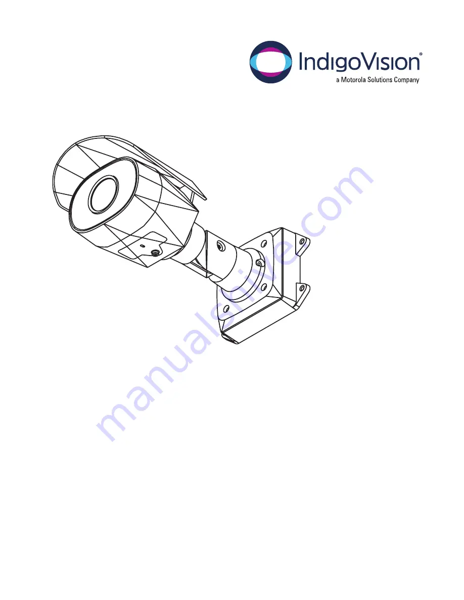
Page 6: ...ints for installing the camera to the mounting bracket 2 Mounting hook slots Points to hold the camera to the mounting bracket while connecting the required cables 3 Mounting holes Holes for securing...
Page 7: ...umber tag Device information product serial number and part number label 3 Camera mounting screws Screws for mounting the camera to the mounting bracket 4 Mounting hooks Hooks to attach the camera to...
Page 8: ...Front View 1 2 1 IR illuminator Provides scene illumination in the IR spectrum 2 Configuration panel cover Covers the configuration panel Front View 3...
Page 9: ...see Optional Configuring microSD Card Storage on page 13 2 Link LED indicator Indicates if there is an active connection in the Ethernet port 3 Connection status LED indicator Provides information abo...
Page 10: ...n shroud An adjustable cover to help protect the lens against glare from the sun 2 Mount arm Adjustable mount arm for positioning the camera 3 Adjustment screws Provides a locking mechanism for the mo...
Page 11: ...ra If the cables for the camera will not be provided from inside the mounting surface install the junction box first BO JCT BOX After you install the junction box you can skip directly to step 3 of th...
Page 12: ...mounting surface 4 Insert the mounting hooks on the rear of the camera into the mounting hook slots on the mounting bracket then let the camera hang Note Before connecting any cables ensure that the...
Page 13: ...camera s audio I O cables For more information see Connecting to External Audio and I O Devices on page 15 7 Install the protective cable boot You may choose to skip this step if you are using the op...
Page 14: ...Connect the network cable to the camera s Ethernet port 9 Tuck the extra lengths of cables into the cable entry hole 10 Raise the camera until it covers the mounting bracket Mounting the Bullet Camera...
Page 15: ...cover from the configuration panel Initializing a Camera Username and Password The camera is not supplied with default username or passwords These need to be provided during initial configuration Imp...
Page 16: ...o choose an IP address When set using Zeroconf the IP address is in the 169 254 0 0 16 subnet The IP address settings can be changed using one of the following methods l Device s web browser interface...
Page 17: ...as you aim the camera 1 Loosen the adjustment screw closest to the mounting bracket to rotate the camera arm 2 Loosen the center adjustment screw to tilt the camera 3 Loosen the adjustment screw on th...
Page 18: ...t meet the recommended write speed the recording performance may suffer and result in the loss of frames or footage 1 Insert a microSD card into the camera CAUTION Do not force the microSD card into t...
Page 19: ...more information see the IndigoVision Camera Web Interface User Guide For More Information Additional information about setting up and using the device is available in the following guides l IndigoVis...
Page 20: ...LPS rated 48 VDC 9 W min External audio and I O devices are connected to the camera through the audio and I O wires The pinout for the wires is shown in the following diagram 1 Grey Audio Input line...
Page 21: ...wing table describes what the LED indicator shows Connection State Connection Status LED Indicator Description Obtaining IP Address One short flash every second Attempting to obtain an IP address Disc...
Page 22: ...e revert button is shown in the following diagram Figure 1 The firmware revert button in the Configuration Panel 1 Ensure the device is powered on 2 Using a straightened paperclip or similar tool gent...
Page 23: ...Camera Web Interface User Guide 1 Locate and make note of the MAC Address MAC listed on the Serial Number Tag for reference 2 Open a Command Prompt window and enter the following commands a arp s New...