background image

6A

6B

01

01

02

1

7

EN

EN

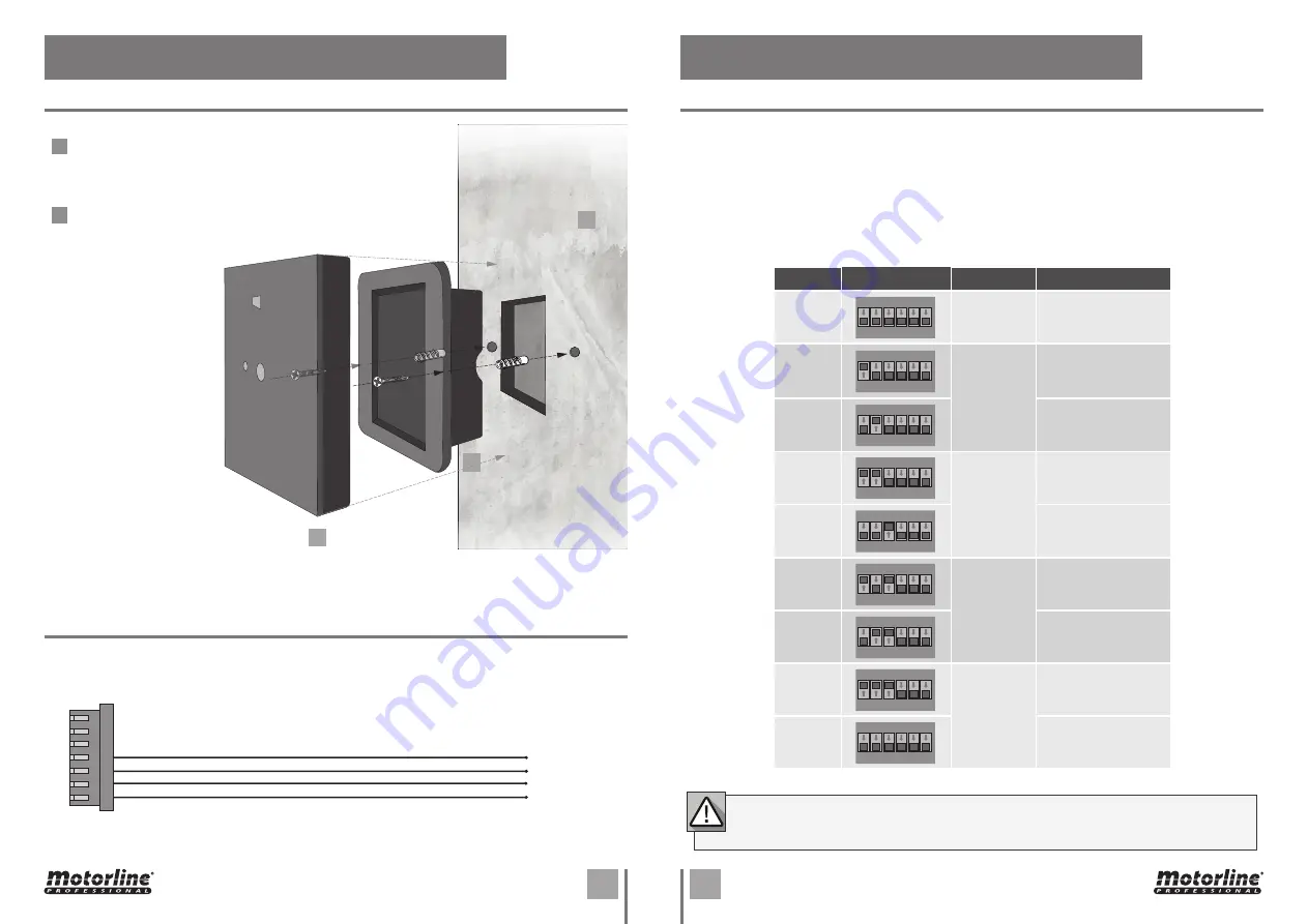
Screw the back into the wall and use the wall-mounted screws for fixing them. (Use your 

own bushings)

Mount the MPXRQ1MWS terminal on the back.

485 A (blue)

+12V (red)

GND (black)

485 B (yellow)

1

2

04. DIP SWITCH

DIP SWITCH CONFIGURATION

In order for the control centre to be able to identify the task of each of the interconnected readers in an 

access control system, each of these devices must have a unique identification ID.

This ID is crucial to identify the task that each device performs and which port/access is installed.

The definition is made through the existing dip switch frame on the back of each reader, according to 

the following table:

ID

Dip switch

Door

Function

No ID

ON

1 2 3 4 5 6

-

-

1

ON

1 2 3 4 5 6

Door 1

Entry

2

ON

1 2 3 4 5 6

Exit

3

ON

1 2 3 4 5 6

Door 2

Entry

4

ON

1 2 3 4 5 6

Exit

5

ON

1 2 3 4 5 6

Door 3

Entry

6

ON

1 2 3 4 5 6

Exit

7

ON

1 2 3 4 5 6

Door 4

Entry

8

ON

1 2 3 4 5 6

Exit

If you connect two or more devices with the same ID in a central, it will create a communication 

conflict and none will work correctly.

RS485 output and power input:

CABLES DESCRIPTION

INSTALLATION OF WALL-MOUNT

03. INSTALLATION

Summary of Contents for MPXRQ1MWS

Page 1: ...V1 0 REV 02 2021 MPXRQ1MWS MPXRQ1MWS EN USER S AND INSTALLER S MANUAL...

Page 2: ...ries eg Charger USB cable electronic material controls etc should not be disposed of as other household waste at the end of its useful life To avoid possible harm to the environment or human health re...

Page 3: ...of the product in a safe manner and who understands the risks and dangers involved Children shouldn t play with the product or opening devices to avoid 01 SAFETY INSTRUCTIONS the motorized door or ga...

Page 4: ...r modification unlock the automatism turn off the power and do not use it until all safety conditions have been met In the event of tripping of circuits breakers of fuse failure locate the malfunction...

Page 5: ...ered cards that is part of the control and management of access of a given location TECHNICAL CHARACTERISTICS BASIC CONTENT 01 01 MPXRQ1MWS 02 01 Embedding MPXRQ1MWS 03 02 Screw for fixing to the wall...

Page 6: ...1 2 3 4 5 6 7 8 24mm 38mm 86mm 14mm 86mm 65mm EN Indicator LED 14 Pin Conectors RS485 Power Supply Input ID Setting MIFARE Card Area QR Code Area FRONT SIDE BACK 02 PRODUCT DIMENSIONS AND PRODUCT DIA...

Page 7: ...he task that each device performs and which port access is installed The definition is made through the existing dip switch frame on the back of each reader according to the following table ID Dip swi...

Page 8: ...3 OK2 OK1 ERR2 BZ2 EXTERNAL POWER CONNECTION 12Vdc Red 12Vdc Red RS485 RXD Blue RS485 TXD Yellow GND Black GND Black Recommended power supply 12Vdc 10 at least 500mA Comply with IEC EN 60950 1 standar...

Page 9: ...IONS FOR FINAL CONSUMERS SPECIALIZED INSTALLERS DEVICE TEST To avoid self sensing interference from the touch sensor please do not touch the sensor when turning on the device power 1 When the power is...

Reviews: