
16A
16B
15A
15B
EN
EN
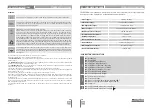
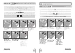
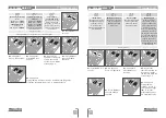
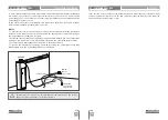
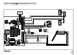
To detect which components have problems in an electromechanical barrier installation,
sometimes is necessary to conduct tests with a direct connection to a 110V or 230V
power supply. For it is necessary to connect capacitor between the automation and the
power supply in order to test.
In the scheme below it is shown how this connection should be done and how the
different component wires should be connected.
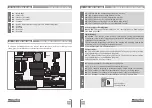
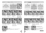
NOTES
:
• To perform the test it is not needed to remove the automatism from the instalation,
because in this way it’s easier to understand if the automatism connected directly to
the power supply can function correctly;
• The linking order between the capacitator and the automatism wires is not important,
as long as it is connected, one with the brown wire and the other with the black wire;
• The common wire must always be connected to the power supply.
• To reverse the automatism operating direction just swap the automatism black wire
with brown wire in the power supply direct’s connection.
All tests must be carried out by specialized technicians due to the serious
danger related to the misuse of electrical systems!
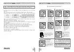
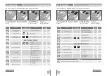
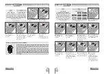
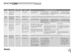
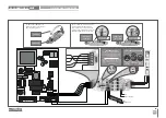
In the position corresponding to each transmitter input in low voltage, the control board has
a LED to identify the condition of it. The LED on indicates that the input is closed, while the
LED off indicates that the input is open.
SCHEME FOR CAPACITATOR
INPUTS TEST
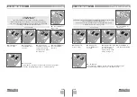
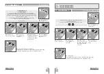
07. COMPONENTS TEST
07. COMPONENTS TEST
BARRIER
Common (Blue)
Black
Brown
POWER
SUPPLY
110V or 230V
CAPACITOR
10μF (230V)
25μF (110V)


