© Motor City Wash Works, Inc. 48285 Frank, Wixom Michigan 48393 U.S.A.
Phone: 248.313.0272 ▪ Fax: 248. 313.0271
8MANULALTINS001 10-15-2020
www.motorcitywashworks.com
2
Installation Procedures:
Upon
receiving your MCWW Alternator Enclosure, open the box and verify that you have all the
required components as well as there are no damages to the equipment. Verify also that you have
all your installation material.
Mount
the Control Panel in the mechanical room or on any wall in a
CLEAN, DRY AREA.
Secure
the panel to the wall using the 1/4” mounting hole in the four mounting brackets.
Pull
and
connect
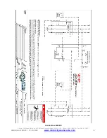
field installed wiring from the L1 and L2 legs of power from each compressor
to alternator enclosure as shown in drawing below.
Pull
and
connect
field installed wiring from both compressors to alternator unit within enclosure
as shown in drawing below.
Pull
and
connect
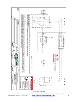
field installed wiring in-between both compressors as shown in drawing below.
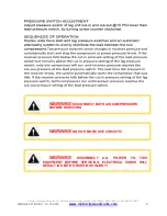
Set pressure switch ON/OFF on Load 2 (Compressor 2) to 10 PSI lower than Load 1 (Compressor
1). For example: Compressor 1 is set to 140/110PSI for ON/OFF, Compressor 2 should be set
to 130/100PSI.
Start-Up Procedures:
Turn
ON
power to compressors and alternator enclosure. Verify alternator has power and that
Load 1
(Compressor 1)
is on.
Compressor 1 must be wired to Load 1.
Once
Load 1
(Compressor 1) is running and hits its high limit (in this case 140PSI) it will turn
OFF.
The next time pressure drops, it will turn
ON
the idle compressor (
Load 2,
Compressor 2).
Load 2
(Compressor 2) will run until the high limit of the lead pressure switch is reached again.
If the pressure drops below the lag pressure switch low limit (in this case 100PSI), both
Load 1
&
Load 2
(Compressors 1 & 2)
will turn on to bring pressure back into range. This process will
continue to go back and forth reaching the lead pressure switch’s high limit.
Note: Both compressors will never be on at the SAME TIME unless Load 2 (Compressor
2) pressure switch has hit its LOW limit, in which case both Loads (Compressors) will turn
on to compensate and try to bring pressure back up into range.

