background image


4.

最大直

最大直

额定电

MPPT

最大

MPP

单个

M

最大


4.2

最大交

最大交

额定

技术参

1 输入

Model 

直流输入功

率(

W


直流输入电

Vdc


电压(

Vdc


T

电压范围

Vdc


大输入电流


PT

路数

 / 

MPPT

串数


大短路电流

A


2 输出

Model

交流输出功

(KW) 

交流视在功

(kVA) 

定交流电压

(Vac) 


参数 

(直流)

ST5KT

7500

1100

630

200-95

22/22

2/2

30 

(交流)

ST5KTL


11


表格

TL ST6

90

11

6

50 200


22

2

3


表格

ST6K

6KTL 

000 

100 

630 

0-950 

2/22 

2/2 

30 

KTL ST

3/N/PE/230

ST7KTL 

10500 

1100 

630 

200-950 

22/22 

2/2 

30 

T7KTL 

0/400 

ST8KTL

12000 

1100 

630 

200-950

22/22 

2/2 

30 

ST8KTL 

Summary of Contents for ST5KTL

Page 1: ...ST5KTL ST6KTL ST7KTL ST8KTL V2 0...

Page 2: ......

Page 3: ...4 4 4 5 6 7 7 7 7 7 7 7 8 8 8 1 2 3 1 3 1 1 3 2 1 3 3 1 2 3 6 1 2 3 4 1 2 3 4 5 6 1 2 I 1 1 1 1 1 2 3 6 6 6 7 7 9 11 11 11 12 13 14 15 16 16 17 18 18 20 21 22 22 22 1 1 1 1 1 2 3 6 6 6 7 7 9 1 1 1 2 3...

Page 4: ...3 P 4 8 4 1 8 4 2 1 LED 9 1 1 LED1 9 1 2 LED2 9 1 3 LED 2 9 2 1 9 2 2 0 1 0 2 10 2 1 RS4 10 2 2 WiF 2 1 2 2 2 3 2 4 PV 85 i II 23 23 24 27 29 29 30 33 33 33 34 34 34 35 36 38 38 38 38 40 42 44 44 44 4...

Page 5: ...1 1 1 1 2 1 3 1 3 A 1 2 3 1 ST5 8KTL L B ST5 8 1 ST5KTL KTL C 1 L ST6KTL ST7KTL D ST8KTL...

Page 6: ...1 3 2 2 IEC 617 730...

Page 7: ...1 3 3 D DC D 3 DC DC 5...

Page 8: ...4...

Page 9: ...C TU CQ E UV QC 5 CE TUV CQC...

Page 10: ...2 2 2 2 1 2 6 2 3...

Page 11: ...2 3 1 2 3 4 5 6 7 2 6 3 1 2 3 4 5 6 7 6 WiFi GPRS RS485 LCD 7 4 M W R 4 MPPT WiFi RS485 MPPT GPRS PV1 PV2...

Page 12: ...S 5 ST5K ST5KTL 24kg 8 KTL ST6KT ST6KTL 24kg TL ST7KTL 1 L ST7 24 ST8KTL 7KTL 4kg ST8KTL 24kg...

Page 13: ...3 A B C D E F G RS 9 2 S485 1 1 4 8 4 2 1...

Page 14: ...A D G 10 6 B E 6 C F...

Page 15: ...ac ST5KT 7500 1100 630 200 95 22 22 2 2 30 ST5KTL 5 5 11 TL ST6 90 11 6 50 200 22 2 3 ST6K 3 6KTL 000 100 630 0 950 2 22 2 2 30 4 KTL ST 6 6 3 N PE 230 ST7KTL 10500 1100 630 200 950 22 22 2 2 30 T7KTL...

Page 16: ...M MP Hz A cos 3 Model PPT 50 60 8 3 ST5KT 98 5 98 1 99 9 12 0 50 0 8 TL ST6 98 98 99 0 60 10 8leading 0 8 3 5 6KTL 8 5 8 1 9 9 50 60 11 8lagging 3 ST7KTL 98 6 98 3 99 9 50 60 12 3 ST8KT 98 6 98 3 99...

Page 17: ...4 4 M W H IE IEC 6 4 Model H D mm kg C C60529 60721 3 4 W ST5KT 13 TL ST6 25 RS485 6 6KTL 430 550 24kg 60 45 IP65 I 4K4H 1W LED LC 0 100 WiFi 5 ST7KTL 180 5 CD GPRS ST8KT L...

Page 18: ...5 WiFi RS 14 S456 GPRS...

Page 19: ...6 15 7 7...

Page 20: ...7 7 1 16...

Page 21: ...7 2 45 C 2 C 60 C 17 2000 8 15 25 C 11 60 C...

Page 22: ...7 3 7 4 3 4 4 18 9 10 8mm m...

Page 23: ...40 8 10mm 45mm m 19 11 12...

Page 24: ...7 5 5 14 20 13 4...

Page 25: ...7 6 6 LCD D 21...

Page 26: ...8 8 8 2 A B C D E F 1 2 RS W S485 WIFI 22 15 7...

Page 27: ...8 3 8 3 3 P 1 MPPT PV T 23 MPPT PV 16 V1 PV2 MPP PT...

Page 28: ...MPP 8 3 1 100 V PT 2 17 M DC 23 MC4 MC4 24 PV MPP IP68 4 MPP 22 A V1 PT A DC PV2 MC4...

Page 29: ...1 2 3 4 5 7 25 17 18 19 7 8 9...

Page 30: ...6 7 8 2 6 2 9 9NM 26 20 2 0 1 22 23...

Page 31: ...8 3 3 P PV PV 27 V 110 27 00Vdc O OFF...

Page 32: ...PV PV PV 24 25 26 IP65 V 28 5 PV 6 PV IP68 OF FF 1 3 2...

Page 33: ...8 4 8 4 4 1 S L1 8 ST5KTL 4mm 2 10A 10 12mm L2 L3 N 29 8 ST6KTL 4mm 2 16A 14 7 7 L ST7 1 25mm 7KTL 4mm 2 16A 7 ST8KTL 6mm 2 16A...

Page 34: ...8 4 2 30 1 5 4 2 5...

Page 35: ...4 2 2 28 29 31 27 30 30 31 2 29...

Page 36: ...32 30...

Page 37: ...9 9 9 1 1 LED 1 1 LED1 Off On 33 LED 31 9 9 M MPPT...

Page 38: ...9 1 9 1 9 2 1 2 LED2 1 3 LED3 2 LCD Off On Off On LCD 34 10 1 32 0 1 L 30 LCD LCD LCD...

Page 39: ...9 2 2 1 3 88 44 6688 8 0 35 33 LCD 4 kWh kWh 0 w 34 2013 0 5 10 15 20 5 8 kw 4 02 20 18 8 11 14 1 Today 18 18 17 20 h y...

Page 40: ...9 2 2 2 1 F 1 F01 F09 F10 F11 F13 F14 F15 F16 F13 1 LCD 36 35 12 2013 0 5 2 PV1 PV2 ARM 02 20 18 18 18...

Page 41: ...F17 F18 F20 F25 F27 F28 F29 F30 F33 F36 F49 F51 F52 F62 F63 F65 F66 37 PV1 PV2 Boost AD ARM...

Page 42: ...10 10 10 10 RS4 1 2 2 1 RS4 485 RS485 RS485 RS 85 1 38 S485 R 1 1200 S485 0m RJ45 WiFi G GPRS 32...

Page 43: ...8 RJ45 1 2 3 4 5 6 7 8 RS485 W Webbox 39 36 RS485 37 8 13 8 VCC VCC NC GND GND NC A B 5 RJ45 RJ45 Webbo ox...

Page 44: ...10 2 2 WiF WiFi WiFi 38 RS48 i W 40 Web 5 USB 39 RS485 WiFi W bbox P PC WiFi PC...

Page 45: ...Wi Wifi ifi 41 40 W 41 Wifi Wifi Wifi...

Page 46: ...11 LED3 42 14 LCD...

Page 47: ...DC 14 C 43...

Page 48: ...12 12 12 12 13 12 1 2 3 F to 158 4 24 F 44 25 5 70...

Page 49: ...13 S 400 ST5KTL ST 756 5188 a b c d e T6KTL ST7 45 7KTL ST8K 5 KTL...

Page 50: ...1061 400 756 5188 86 755 2765 7908 www mosopower com sales solar mosopower com 400 756 5188 86 755 2765 7908 service solar mosopower com...

Page 51: ...Solar On Grid Inverter ST5KTL ST6KTL ST7KTL ST8KTL User Manual Version 2 0 EN...

Page 52: ...f this manual are owned by MOSO Power Supply Technology Co Ltd hereinafter MOSO No part of this document can be modified distributed reproduced or published in any form or by any means without prior w...

Page 53: ...DIAGRAM 8 2 3 PRODUCT INSTRUCTION 9 2 4 DIMENSION AND WEIGHT 10 3 PACKAGING LIST 12 4 TECHNICAL DATA 14 4 1 INPUT DC 14 4 2 OUTPUT AC 15 4 3 EFFICIENCY SAFETY AND PROTECTION 15 4 4 GENERAL DATA 16 5 F...

Page 54: ...tion Procedure 35 9 OPERATION 37 9 1 LED DISPLAY 37 9 1 1 DC DC status LED 1 Green 38 9 1 2 DC AC status LED 2 Green 39 9 1 3 Fault LED 3 Red 39 9 2 LCD DISPLAY 39 9 2 1 System Page 40 9 2 2 Message P...

Page 55: ...s manual is applicable to the following inverter types ST5KTL ST6KTL ST7KTL ST8KTL 1 2 Target Group This manual is intended for Qualified personnel who are responsible for the installation and commiss...

Page 56: ...nstallation debug and maintenance should be operated by qualified and accredited technicians Child people with limited capacity or mental disorder is forbidden to operate the inverter People who lacks...

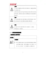
Page 57: ...er voltage may cause permanent damage to inverter or other losses which will not be included in warranty Warning Authorized service personnel must disconnect both AC and DC power from the ST series in...

Page 58: ...during operation Install the inverter where is not accessible for children Risk of electric shock Do not disassemble the cover of the inverter Only authorized personnel can be allowed to inspect or m...

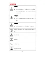
Page 59: ...information on operating the buttons refer to Section 7 2 LCD display Recovery and recycling Symbols on the type label Symbol Explanation CE mark The inverter complies with the requirements of the ap...

Page 60: ...ction 2 1 Overview The image shown here is for reference only The actual product you receive may differ Figure 2 Stereogram 2 2 Electrical Block Diagram Electrical block diagram Figure 3 Electrical bl...

Page 61: ...PV strings and the inverter safely 2 PV Terminals ST Series Inverters have two independent MPP trackers PV1 and PV2 Per tracker has two PV input terminals 3 WiFi Terminal Terminals connect the WiFi m...

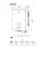
Page 62: ...10 internal 6 AC Terminals AC output 7 LCD Display The display shows the status information e g working status power input voltage as well as errors and disturbances 2 4 Dimension and Weight Dimension...

Page 63: ...11 Figure 5 ST5KTL ST6KTL ST7KTL ST8KTL Weight Table 1 Model ST5KTL ST6KTL ST7KTL ST8KTL Weight 24kg 24kg 24kg 24kg...

Page 64: ...ame Quantity A Solar Inverter 1 B Mounting Frame 1 C expansion bolt 4 D PV connector plug bolt 8 E plug bolt 4 F RS485 connector 2 G User Manual 1 The ST series inverter is shipped with the following...

Page 65: ...i Check the d visible exter f the delive A D G 13 Figure ter ter by the n side of the odel seria stics are sp delivery for rnal damag ry is incomp B E 6 ameplate T housing l number s pecified on t com...

Page 66: ...ax DC power 7500 W 9000 W 10500 W 12000 W Max DC voltage 1100 V Start voltage 160 V MPPT voltage range 200 950 V Rated input voltage 630 V Number of MPPTs 2 2 2 2 Max number of strings 2 2 2 2 2 2 2 2...

Page 67: ...V 400V AC voltage range 310 480 V Conform to local standards Rated AC grid frequency 50Hz 60Hz Max output current 8A 10A 11A 12A Adjustable power factor 0 8leading 0 8lagging Max total harmonic distor...

Page 68: ...Switch Yes DC reverse polarity protection Yes DC surge protection Yes Insulation monitoring Yes AC overcurrent protection Yes AC surge protection Yes Anti islanding protection Yes Residual current mon...

Page 69: ...5 WiFi opt GPRS opt Dimension W H D 430 550 180 mm Weight incl mounting bracket 24 kg Degree of protection IP65 Warranty 5 years 10 years opt 15 years opt 5 Function Description The basic functions of...

Page 70: ...interface You can choose the RS485 terminal for connecting a communication module to the PV system such as Wi Fi module Protective function The protective functions are integrated in the inverter inc...

Page 71: ...etting injury by improper carry Select a firm mounting surface Use proper tools for installation At least two people are suggested to coordinate for the installation CAUTION HOT NOTICE The inverter ou...

Page 72: ...t temperature should not exceed the working temperature of the inverter 25 to 60 derating between 45 to 60 Do not install the inverter at altitude of above 2000m otherwise the inverter will derate Do...

Page 73: ...t sunlight as this can cause excessive heating and thus power reduction In living areas do not mount the unit on plasterboard walls or similar in order to avoid audible vibrations When in use the inve...

Page 74: ...etween the inverters and ensure an adequate fresh air supply This will prevent a reduction in inverter power as a result of excessively high temperatures details on temperature derating can be found i...

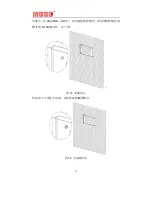
Page 75: ...nverter Install the inverter with good ventilation condition Figure 11 Align the wall mounting bracket horizontally on the wall with the arrow upwards Mark the position of the drill holes Drill the ma...

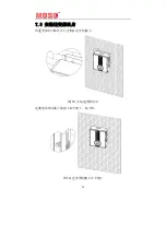
Page 76: ...24 Figure 12 7 5 Fixed the Inverter on the Wall Mount the inverter to the bracket Figure 13...

Page 77: ...tus Check the upper straps of Inverter to ensure it fixed on to the bracket Check the secure mounting of the PV Inverter by trying to raise it from the bottom The PV Inverter should remain firmly atta...

Page 78: ...components of the inverter can be irreparably damaged by electrostatic discharge Earth yourself before touching any components 8 2 Overview of the Connection Area Figure 15 Table 7 Object Description...

Page 79: ...to four strings can be connected in total Requirements for the PV strings Same type Same number of in series connected PV modules Identical alignment Identical tilt The cables of PV modules connectio...

Page 80: ...mak hes the DC 28 cuit voltage m input volta Maxim V connectio itive pole of pole of the a mixed con connected with two pair will not com on the electr s operating he DC C on Figure 2 connector or und...

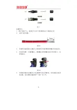
Page 81: ...protective sleeve of the cable and leave the bare cooper conductor in 7mm Fugure 18 3 Insert the bare cooper conductor into the pin and make sure no bare cooper conductor is exposed outside 4 User a...

Page 82: ...e is a click sound Fugure 22 8 Using a wrench to take apart the connection when it is necessary Fugure 23 8 3 3 Connecting the PV Array DC DANGER Danger to life due to high voltages Before connecting...

Page 83: ...multimete odule is less 31 ltages wou DC input vo uld be over DC input by 25 Figure y of the out symbols r to make s s than the m uld damage oltage rang 1 000 Vdc y turning the 24 put voltage sure th...

Page 84: ...y of erter connec inputs shou with plugs sure all the 32 Figur e the PV str the PV mod ctor Figure uld be conn to make su connectors re 25 rings are no dule output 26 nected with ure the prot s are we...

Page 85: ...ulti core c 25 mm s section re ripping cabl to Table 7 ion of micr connect the 33 onnectors a a long time o Grid or AC Co e connection able and MC L ST6K m2 4m 10 cable The d efers to Tab le 10 12 m t...

Page 86: ...ters to one MCB Select the MCB according to the max output current of the inverter In general the nominal current is 1 5 times more than the max output current of the inverter DANGER Danger to life du...

Page 87: ...onnect the three phase MCB and make sure it is not connected again Take out the screws of the AC output terminals refer to figure 27 Figure 27 Cable gland Figure 28 Cable through gland Unscrew the scr...

Page 88: ...conductors L and N must not be swapped Figure 30 NOTICE Risk of fire if two conductors are connected If two conductors are connected to one terminal this may result in a poor electrical contact which...

Page 89: ...ay There are three LED indicators on the panel DANGER Danger to life due to high voltages in the inverter Do not switch on the miniature circuit breaker until the PV array has been connected and the i...

Page 90: ...38 Figure 32 9 1 1 DC DC status LED 1 Green Table 9 Off The DC DC circuit is off Blinking The DC DC circuit starts On The DC DC circuit is working normally...

Page 91: ...ht which indicates that the inverter is feeding electricity to the grid 9 2 LCD Display The LCD displays the inverter status and the collected data for assessing system performance Figure 33 The displ...

Page 92: ...m 9 2 1 System Page Figure 35 Power the present power feeding into the grid Today Energy exports to the grid in the present day and updates the data every 10 minutes Total Sum of the energy exports to...

Page 93: ...this page will be blank 9 2 2 Message Page Figure 36 The system status is shown on the page of MESSAGE The first line will show the operation mode like waiting mode self testing mode on grid mode and...

Page 94: ...t F26 Bus Volt Low Fault F27 Bus Un Balance F28 Bus Ovp Fault F29 Ocp Ac F30 Ocp Boost F32 IAC_ RMS_ Unbalance F33 DCI Gird over limit F36 GFCI Fault F49 Pv Config Set Wrong F51 Unrecover Phase Sequen...

Page 95: ...inverter or multiple inverters In general RS485 can be used for the communication with up to 32 units The length of cables should be within 1200 meters Select high quality network cable peel the isol...

Page 96: ...37 Communication Interface of ST Series Inverters Figure 38 8 line RJ45 Table13 8 line RJ45 8 line RJ45 Wire No Function Wire Color 1 VCC Orange white 2 VCC Orange 3 NC Green white 4 GND Blue 5 GND Bl...

Page 97: ...he n method b n cables a ossover cab Figure 39 W e system to 45 A B between R are used f ble is used Web Box Mo o PC by RS RS485 and W for connec to connect onitoring Dia S485 USB A Brown w Brow Webbo...

Page 98: ...WiFi module from the ma 1 WiFi interf r to the WiF d fault LED en will disp e for a list o ooting 40 onal only applica e is built in a anufacturer face Fi configur If the inver properly p following i...

Page 99: ...ng voltage exceeds the input voltage of the inverter Call the local service office DCI Gird over limit Disconnect the PV PV with DC input then reconnect them Check L line and N line to see whether it...

Page 100: ...C output Wait for 5 minutes Remove all connected cables from the inverter Remove the inverter from the bracket 12 2 Package The original package is encouraged to use again to pack the inverter Or use...

Page 101: ...oducts ST5 6 7 8KTL Limited Product Warranty Only applicable for inverters under normal application installation use and service conditions ST Series Inverters warrants the above listed products to be...

Reviews: