2
• Shipbuilding
• Machinery
• Paper-making
• Textile
• Geothermal utilization
• Environmental protection
• Refrigeration, etc.
4.
The Plate exchanger transfers heat three to five times more efficiently than a tube-in-tube exchanger. The efficiency of the heat ex-
change can reach above 90%. .
TIP
:
For brewery operations, expect to use one batch size of tap water and one batch size of chilled liquor in 30 minutes to cool one batch
when the pumps and heat exchanger are properly sized. (i.e.: A 10 bbl brewery would use 10 bbl of cooling water and 10 bbl of chilled
liquor to cool 10 bbl of wort).
B. Structure
1.
This Heat Exchanger contains a double bracing frame which consists of the following components:
a.
End Panels
b.
Plates
c.
Exchanger Seals
d.
Top & Bottom Guides
e.
Clamping Bolts
f.
Process Connections For Fluids
C. Plates
1.
The application will determine how many plates a heat exchanger should have. There are gaps between the plates to create flow paths
for the fluids to move through. Seals on the plates allow the two different fluids to go in separate directions while allowing the heat
exchange to occur.
Plates are cut and pressed from a sheet of stainless steel (SUS304) and have corrugated and chevron shapes, which are used for the
following:
• Larger areas of exchange.
• The pressed shapes increase the plates’ stiffness, allowing the two fluids to have different pressures.
• The waves speed up the flow, allowing less debris to accumulate.
• The shape allows for turbulent flow at lower velocities, increasing exchange efficiency.
D. Seals
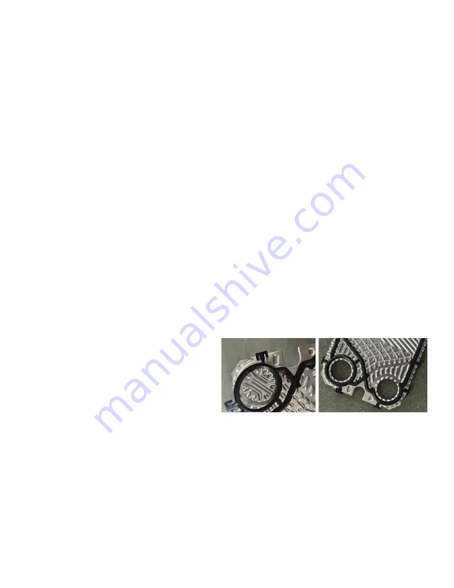
The seals inside the heat exchanger are removable. Seals
should be replaced if there are any signs of cracking. If the
heat exchanger does not seal before the plate’s contact, the
seals must be replaced otherwise, the plates may be damaged
during the tightening sequence. (Metal on-metal operation is to
be avoided.)
E. Operation
The plate exchanger consists of a series of parallel plates that are placed adjacent to each other to allow the formation of a series of chan-
nels for fluids to flow between them. The exchanger is operated with the fluids flowing in opposite directions maximizing the difference
in temperature between the fluids and increasing exchange efficiency.
The plates allow hot and cold fluids through alternating channels in the exchanger so that a plate is always in contact on one side with hot
fluid and the other with cold fluid. During flow, heat exchange will occur through the plates in proportion to the temperature differential
of the two fluids.
See the flow chart on the next page as an example (only one stage is shown):


