background image

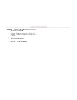
MEASURING CURRENT WITH INTERNAL CURRENT SHUNT 

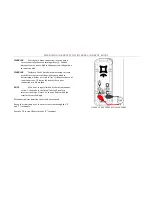
WARNING


Exercise care when connecting in series with a 

circuit, especially those containing motor(s).  Sudden 
disconnects may create higher than expected voltages due 
to inductive kick. 

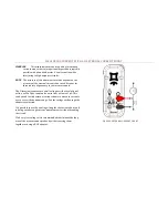
WARNING


Perform a Fuse Check before measuring currents 

with the internal current shunt. Exercise caution in 
determining whether a circuit is “live” if the meter does not 
report a current.  This may indicate either a poor 
connection or a blown fuse. 

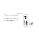
NOTE


AC current range is limited by the instantaneous 

current.  Peaks above the listed limits will result in 
incorrect readings.  Derate AC current limits with high 
crest factors accordingly. 

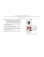
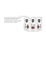
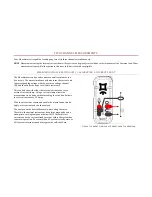
Disconnect power from the circuit to be measured. 

Break the circuit and wire the meter in series through the “A” 
and “C” terminals. 

Positive DC current flows into the “A” terminal. 


FIGURE 2 BASIC CURRENT MEASUREMENT 


Summary of Contents for Mooshimeter BLE-DMM-2X-01A

Page 1: ...MOOSHIMETER USER S MANUAL Mooshim Engineering LLC 2565 3rd St Suite 315 San Francisco CA 94107 August 2014 Rev 1 2014 Mooshim Engineering All Rights Reserved...

Page 2: ...defines a level of safety appropriate for the transient overvoltages present in fixed equipment installations at the distribution level This includes the mains installation of a building distribution...

Page 3: ...least CAT III 600V Keep fingers behind the guards on the leads Use caution working with voltages above 30VAC rms 42VAC peak or 60VDC Voltages this high pose risk of shock Never apply more than 600V b...

Page 4: ...C Common terminal for all measurements A Input terminal for measuring currents to 10A RMS AC and DC V Input terminal for measuring voltages to 600V RMS AC and DC Input terminal for measuring resistan...

Page 5: ...he circuit before assuming the circuit is safe Two of the Mooshimeter s input terminals are capable of making basic voltage measurements The V terminal can measure up to 600V RMS and is intended for t...

Page 6: ...n determining whether a circuit is live if the meter does not report a current This may indicate either a poor connection or a blown fuse NOTE AC current range is limited by the instantaneous current...

Page 7: ...surements The terminal can measure small voltages with a resolution of as fine as 25nV per count and a noise floor as low as 1 V This can be used to with external current shunts to measure currents ov...

Page 8: ...ay engage the internal protection circuitry Should this occur wait 5 minutes before taking further measurements Resistance is measured between the and C terminals Polarization is not important The met...

Page 9: ...nal protection circuitry Should this occur wait 5 minutes before taking further measurements To test diodes or other silicon junction devices a test current is pushed through the device under test and...

Page 10: ...standard BNC adapter Measurements using the A or terminals can be used with the C terminal as usual To use a BNC adapter with the V input use the A terminal as the common input The A and C terminals a...

Page 11: ...en finds the slope to calculate resistance This can be done with either the internal current shunt or an external current clamp Using a current clamp allows the measurement to be done without breaking...

Page 12: ...urement requires voltage and current measurements Current measurement can be done with either internal or external current shunt mode Power Factor is a unitless measure so the gain accuracy of the mea...

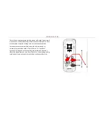
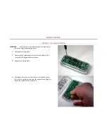
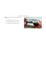
Page 13: ...ning the meter 1 Disconnect all test leads 2 Unscrew both retaining screws from the bottom of the case with a Phillips head screwdriver 3 Separate the two halves 4 Taking special care not to bend the...

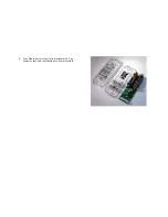
Page 14: ...5 Your Mooshimeter is now fully disassembled The batteries fuse and reset button are now accessible...

Page 15: ...shock Do not operate the meter while partially disassembled 1 Place the PCB in the bottom enclosure half Use the J shaped fin for alignment with the corresponding cut out in the PCB 2 Close the two ha...

Page 16: ...ty the Mooshimeter s LED will blink slowly several times before turning off If the light does not blink check the battery polarity 5 Close the Mooshimeter per directions above CLEANING Gently wipe the...

Page 17: ...ter is not accurate below 1 The actual resistance of the fuse should be 20m FIGURE 8 FUSE TEST FUSE REPLACEMENT WARNING Only use appropriately rated replacement fuse 1 Open the Mooshimeter per directi...

Page 18: ...er SD cards or cards formatted differently cannot be written to 1 Open the Mooshimeter per the directions above 2 Press the SD card further into the slot until you feel a click 3 Release The SD card w...

Page 19: ...IMETER WARNING To avoid electric shock disconnect all leads from the meter 1 Open the Mooshimeter per the directions above 2 Press and Hold the button shown for 5 seconds 3 Close the Mooshimeter per t...

Page 20: ...ing Altitude Up to 2000m Maximum Temperature Range 5C to 40C Nominal Temperature Range 18C to 28C Derate accuracy outside of this range Input Power 3V 100mA from installed batteries Battery 2x AA Alka...

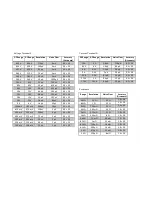
Page 21: ...0 5 20 500 mV 350 mV 100 nV 4 V 0 5 20 400 mV 275 mV 75 nV 3 V 0 5 20 280 mV 200 mV 50 nV 2 V 0 5 20 220 mV 150 mV 40 nV 2 V 0 5 20 150 mV 100 mV 25 nV 1 V 0 5 20 Current Terminal A DC Range AC Range...

Page 22: ...0 nV 2 V 0 5 20 220 mV 150 mV 40 nV 2 V 0 5 20 150 mV 100 mV 25 nV 1 V 0 5 20 Diode Voltage Drop Range Resolution Noise Floor Accuracy 2 2 V 300 nV 10 V 1 0 50 1 2 V 150 nV 5 V 1 0 50 825 mV 100 nV 3...

Page 23: ...ons rules This device complies with Industry Canada license exempt RSS standard s Operation is subject to the following two conditions 1 this device may not cause interference and 2 this device must a...

Reviews: