


3
Visionary Move
Assembly Diagram
R
EAD
T
HROUGH
I
NSTRUCTIONS
FROM
BEGINNING
TO
END
BEFORE
STARTING
TO
ASSEMBLE
UNIT
.
To Assemble:
1.) Identify and Seperate all the Parts and Hardware.
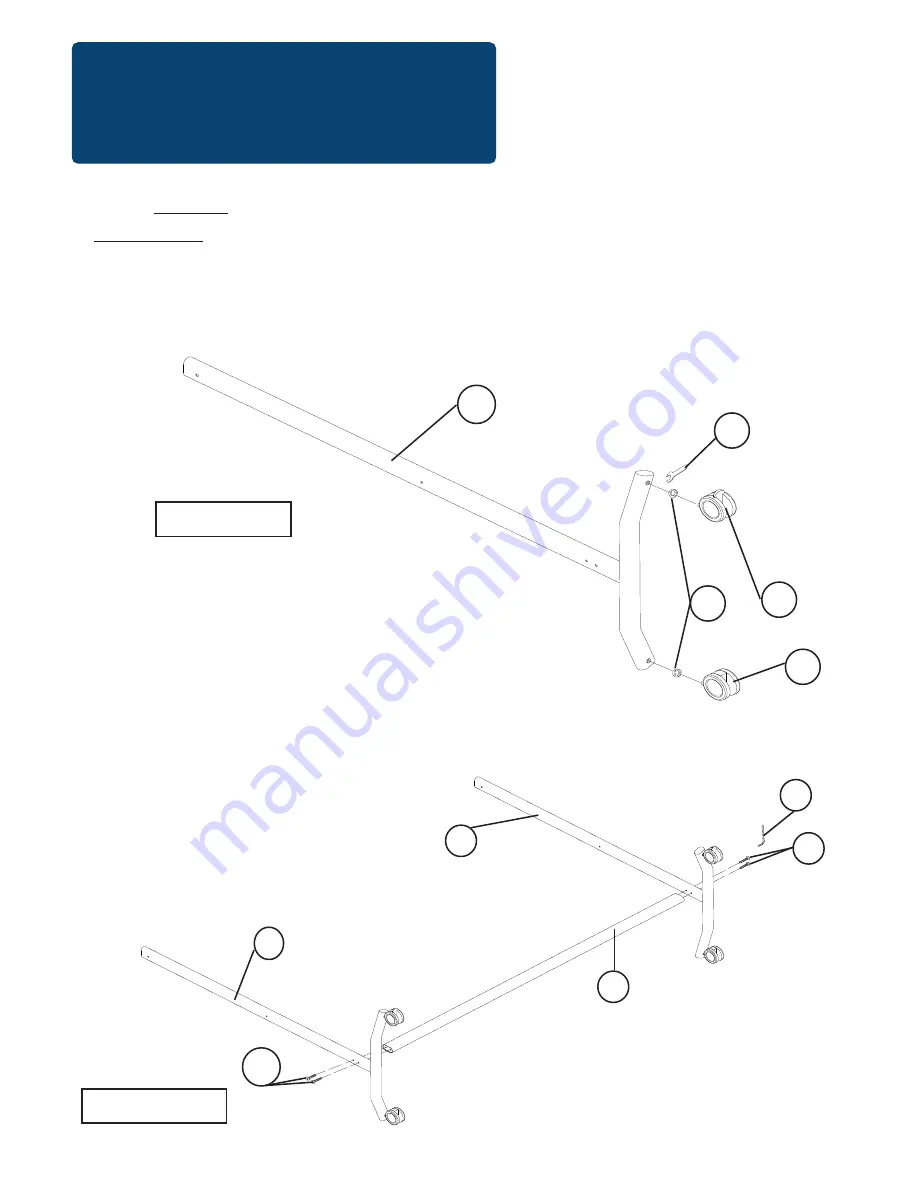
Illustration # 1
2.) Place a Lock Washer (E) on each Caster’s stem and screw in one Locking Caster(C1)
and one Non-Locking Caster (C2) into the bottom of each Leg (P2). Tighten Casters with
Caster Wrench (D) as shown in illustration #1.
C1
P2
3.)
Attach the Bottom Post (P5) in between the Legs (P2) using two Screws (B) for each as
shown. Make sure the feet on the Legs(P2) are point in to each other. Tighten Screws using
Allen Wrench (E). See illustration #2.
P5
B
P2
P2
Illustration # 2
B
D
E
E
C2