background image

5

To Assemble and Attach to Wall:

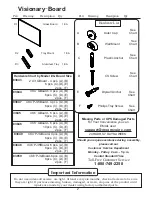
Identify and Separate all the Parts and Hardware.

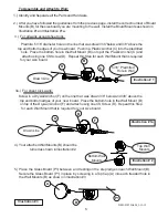
After you have followed the guidelines from the previous page, install the correct number of Board
Mounts (B) for the size board you are mounting to the wall.  Install the Board Mounts as shown in
Illustration #1 and Illustration #1a.

1.)

Illustration # 3

Illustration # 1

2.)

3.)  For all walls except sheet rock:                                                                                               .

                                                                                                            .

   Predrill a  5/16” diameter hole on the line that was drawn 3/8”below and 3/8” above the

 top and bottom edges of your new board.  Push in a Plastic Anchor (C) into the predrilled

 hole.  Place the bottom hole in the Wall Mount (B) on top of the  Plastic Anchor (C) and

attach using one CS Screw (D).  Repeat this Step for each Wall Mount that is required

     for your size board.                   .                                                                                               .

      5/16” Predrilled

  Hole in Wall

Drawn Line

4.)  Your attached Wall Mounts (B) should be

  turned as shown in Illustration #2.

Illustration # 2

Top Wall

Mounts

Bottom Wall

Mounts   .

5.)  Place  the Glass Board (P1) between  and resting on the  step ledge on each Wall Mount (B).

Secure the Glass Board (P1) in place  by screwing in a Top Cap (A) into each treaded hole in

 the Wall Mounts (B) as shown in Illustration #3                                                                                .

P1

B

A

83843-83850ALM_3-13-12

3a.)  For sheet rock walls:                                                                                                      .

                                                                                    .

                                                                                                            .

    Screw in a Drywall Anchor (F) on the line that  was drawn 3/8” below and 3/8” above the

 top and bottom edges of your  new  board.  Place the bottom hole in the Wall Mount (B)

on top of the Drywall  Anchor (F) and attach using one CS Screw (D).  Repeat this Step

 for each Wall Mount that is required for your size board.                               .                   .

.

F

D

B

C

D

B

Illustration # 1a

Drawn Line

Summary of Contents for Best-Rite Visionary BST-83845-XX

Page 1: ...123456789012123456789012 1234567890123456789012345678901212345678901234567890123456789012123456789012 1234567890123456789012345678901212345678901234567890123456789012123456789012 1234567890123456789012345678901212345678901234567890123456789012123456789012 1234567890123456789012345678901212345678901234567890123456789012123456789012 1234567890123456789012345678901212345678901234567890123456789012123...

Page 2: ... Drawing Description Qty Hardware Chart by Model Board Size 2 X3 GBoard 4 pcs A B 6 pcs C D E 3 X4 GBoard 4 pcs A B 6 pcs C D E 4 X4 PJWBoard 4 pcs A B 6 pcs C D E 4 X6 GBoard 6 pcs A B 8 pcs C D E 4 X8 GBoard 8 pcs A B 10 pcs C D E 4 X4 PJGBoard 4 pcs A B 6 pcs C D E 4 X6 PJWBoard 6 pcs A B 8 pcs C D E 4 X6 PJGBoard 6 pcs A B 8 pcs C D E See See See See TM Should you require assistance during ass...

Page 3: ...nd 3 8 below the bottom edge of your board If your wall has studs determine the centerline of the studs It is recommended that you tie into as many studs as possible when mounting your board nstallPreparing to Install Your New Visionary Board NOTE The proper installation of your board will require at least two people Tools required Tape measure chalkline electric drill screwdriver drill and screwd...

Page 4: ...5 3 4 Bottom of Board Line for Board Mounts TrayMount Line C D P2 Push in two PlasticAnchors C into the predrilled holes Place the Tray Mount P 2 over the PlasticAnchors C and secure with two CS Screws D as shown in Illustration 1 3 Illustration 1 Place theAluminum Tray P 3 in the front slot of the Tray Mount P 2 and align the holes Secure theAluminum Tray P 3 to the Tray Mount P 2 using two Phill...

Page 5: ...w D Repeat this Step for each Wall Mount that is required for your size board 5 16 Predrilled Hole in Wall Drawn Line 4 Your attached Wall Mounts B should be turned as shown in Illustration 2 Illustration 2 Top Wall Mounts Bottom Wall Mounts 5 Place the Glass Board P1 between and resting on the step ledge on each Wall Mount B Secure the Glass Board P1 in place by screwing in a Top Cap A into each ...

Reviews: