background image

MC-8 Evolution 

Series


Summary of Contents for Mc-8

Page 1: ...MC 8 Evolution Series Reference Multi Channel Power Amplifier Owner s Manual ...

Page 2: ...MC 8 Evolution Series ...

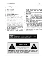
Page 3: ...n or pinched particularly at plugs convenience receptacles and the point where they exit from the apparatus Unplug mains cord during transportation 11 Only use attachments and accessories specified by the manufacturer 12 Use only with the cart stand tripod bracket or table specified by the manufacturer or sold with the apparatus When a cart is used use caution when moving the cart apparatus combin...

Page 4: ... the proper voltage Both the shipping box and rear panel serial number label will indicate the correct voltage Use of any other voltage will likely damage the unit and void the warranty 3 AC extension cords are NOT recommended for use with this product The mains plug of the power supply cord shall remain readily accessible 4 NEVER use flammable or combustible chemicals for cleaning audio component...

Page 5: ...llation Placement 7 Rear Panel Connections 8 Connecting the MC 8 9 Balanced Operation 9 Operating the MC 8 10 Troubleshooting 10 Remote Operation 11 Specifications 12 www simaudio com Simaudio Ltd 1345 Newton Road Boucherville Québec J4B 5H2 CANADA Date Code 20150805 ...

Page 6: ...ully capturing these elusive qualities The information contained in this manual is subject to change without notice The most current version of this manual is available on our official website at http www simaudio com Your MOON MC 8 Multi Channel Amplifier incorporates many significant design features to achieve its world class level of performance This is an abbreviated list of the more important...

Page 7: ...or inside a closed cabinet that is not well ventilated as this could compromise the amplifier s performance and reliability The MC 8 uses a very large toroidal transformer in its power supply even though it is well shielded you should not place this amplifier too close to source components sensitive to EMI such as turntables and phono preamplifiers When the amplifier reaches its normal operating t...

Page 8: ...back panel XLR connectors and store them in a safe place These jumpers are required ONLY when using the single ended RCA inputs If you decide to switch to single ended input mode you must reinstall the XLR jumpers between pins 1 and 3 exactly as shown below Figure 2 XLR connector without and with jumper accessory The lower left section has an RS 232 input on a DB9 connector To the right of this co...

Page 9: ...ade the overall sonic performance of your system 3 Connect the supplied AC power cable to the IEC receptacle located on the amplifier s rear panel Ensure that the AC wall outlet you use is a NEMA 6 20 with a functioning ground For the best sonic performance it is preferable that you plug your MC 8 directly into this NEMA 6 20 AC outlet and avoid using an extension cord In the event that you do not...

Page 10: ...owering down your preamplifier Troubleshooting Each red LED located on the front panel indicates the operational status of each channel of your MOON MC 8 When an red LED it begins flashing on and off during use the circuitry is either over heating or has detected the presence of DC in the input signal DC protection LED blinks 2 times Thermal protection LED blinks 3 times Your MOON MC 8 is a smart ...

Page 11: ...Multi Channel Preamplifier Processor and a MC 8 amplifier connected together via their respective 12V triggers The 12V trigger output on the CP 8 is connected to the 12V trigger input on the top MC 8 using a 1 8 mini jack cable When you turn on the CP 8 via remote control or its Standby button the MC 8 will turn on automatically The same rule applies when you put the CP 8 into Standby mode ...

Page 12: ...se Ratio 105dB full power Crosstalk 1kHz 90dB Intermodulation Distortion 0 005 THD 20Hz 20kHz 1 watt 250 watts 0 02 0 05 Power Consumption idle 85 Watts AC Power Requirements 230V 60Hz or 240V 50Hz Shipping Weight Net Weight 240 lbs 108 Kg 170 lbs 76 Kgs Dimensions W x H x D inches cm 17 4 x 13 4 x 21 44 2 x 34 0 x 53 3 Balanced Input Pin Assignment Pin 1 Ground Pin 2 Positive Pin 3 Négative NOTE ...

Reviews: