moog
MSD Servo Drive DC-AC Operation Manual
[
]
Electrical
installation
35
Id.-No.: CA97554-001 Date: 06/2012
3.13 Motor connection
Step
Action
Comment
1.
Specify the cable cross-section dependent on
the maximum current and ambient tempera-
ture.
Cable cross-section according to
local and country-specific regula-
tions and conditions.
2.
Connect the shielded motor cable to terminals
X12/ U, V, W and ground the motor to
.
Mount shield at both ends to re-
duce interference emission. Secure
shield connection plate of motor
terminal X12 by
both
screws.
3.
Wire the temperature sensor (if present) to X5
using separately shielded cables and activate
the temperature evaluation via
D
rive
A
DministrAtor
5.
Mount shield at both ends to
reduce interference emission.
!
ATTENTION!
For terminal X5 it must be ensured that the temperature
monitor used is equipped with a basic isolation in accordance with
61800-5-1 against the motor winding.
NOTE:
In the event of a short-circuit or ground fault in the motor cable, the
power stage is disabled and an error message is generated.
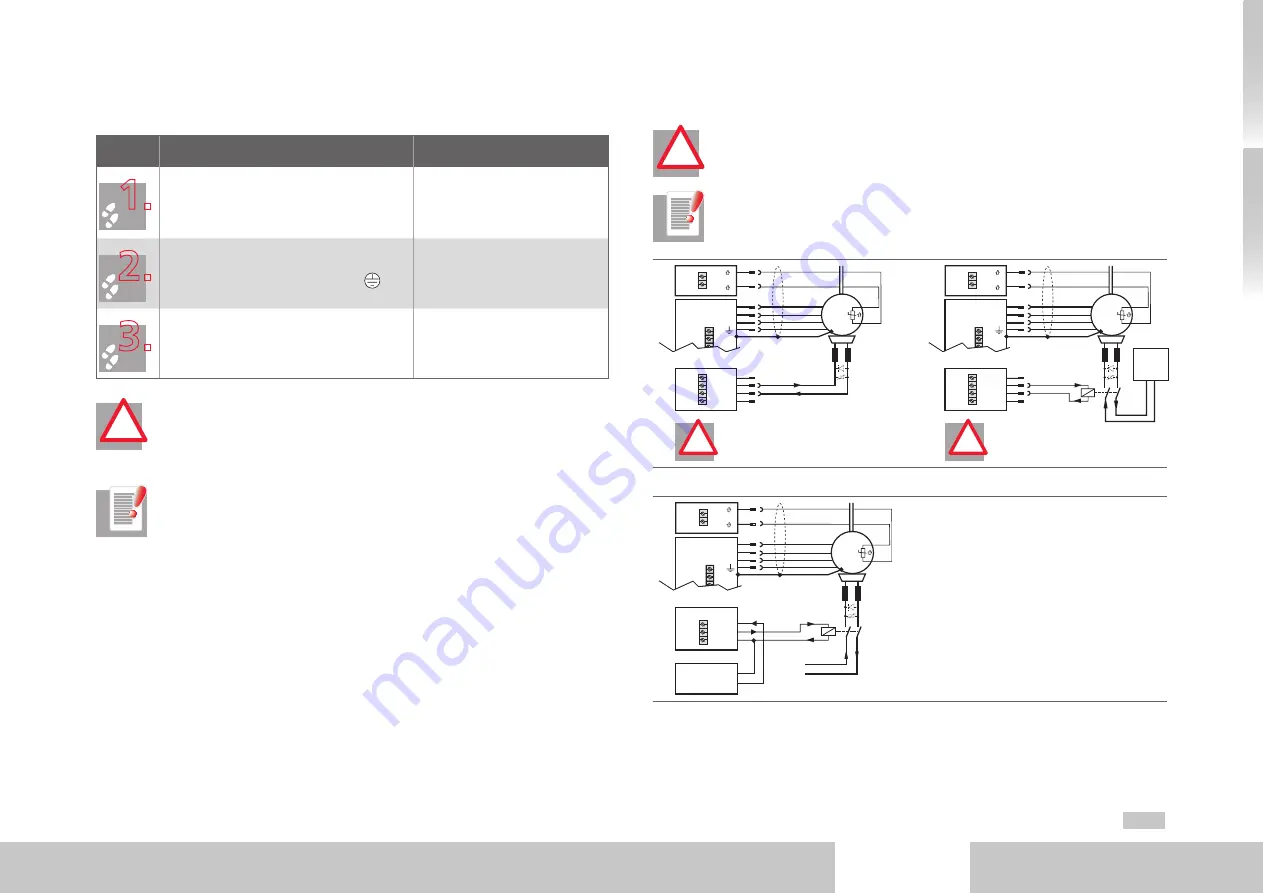
3.13.1 Connection of synchronous motors
!
ATTENTION!
Use only motors permitting connection of the motor tempera-
ture monitor solely to X5 of the DC-AC servo drive. This must be expressly
specified when ordering the motor.
NOTE:
Please use a ready made-up motor cable from Moog GmbH to con-
nect the servo motor series.
Motor
3
U
V
W
+
-
~
X
12
X
5
Motor brake actuation
(max. 2 A)
ATTENTION!
Motor brake
Recommended connection, but only up
to motor brake current
max. 2 A
!
ATTENTION!
Motor brake
• For motor brake current from 2 A
•
No cable break detection!
GND
1
4
3
2
X
13
Motor
3
U
V
W
+
-
~
X
12
X
5
Brakee (+
)
Brake (-
)
Motor brake
actuarion
GND
1
4
3
2
X
13
+24 V DC
Supply for
brake
24 V DC
+
!
!
Fig. 3.13 Connection options of motors Size 1 to Size 4
Motor
3
U
V
W
+
-
~
X
12
X
5
Brake (+)
Brake (-)
Motor brake
actuation
GND
OSD03
+24 V 1
3
-
+
2
X
20
24 V DC supply for
brake
(I
IN
= 2.1 A)
24 V DC
+
Fig. 3.14 Connection of motors Size 5 and Size 6A


