background image


Page 24


Voyager User’s Manual - The Components 


Page 25


Voyager User’s Manual - The Components

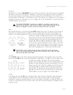
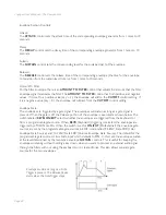
Dual Lowpass Mode:

The Voyager’s Dual Lowpass filter mode features two 
lowpass filters which are routed to the left and right 
audio output, creating a stereo effect.  The 

CUTOFF


knob controls the frequency cutoff of both filters. 
The filters can be set to the same cutoff frequency, 
or adjusted to different cutoff frequencies using the 

SPACING

 control.  When the two filters are set at 

different cutoff frequencies and routed to two different 
speakers, what you hear can be a fantastically swirly 
and vocal sound – similar to a phaser effect.  In Dual 
Lowpass mode, the

 RESONANCE

 control affects both 

filters identically.

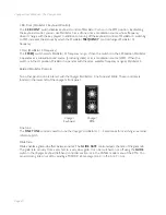
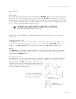
Highpass Lowpass Mode:

In Highpass/Lowpass mode, the Voyager’s filters are 
configured as a lowpass and highpass filter in series, 
resulting in a bandpass filter.  The output of the 
bandpass filter is routed to both outputs.  As with the 
Dual Lowpass mode, the 

CUTOFF

 control changes 

the cutoff frequency of both filters, and the 

SPACING


control sets the frequency difference between the 
highpass filter and lowpass filter.  The spacing between 
the two filters creates a variable passband.  In this mode, 
the

 RESONANCE

 control affects only the lowpass filter, 

thus making for some distinctive and ususal filter sounds.

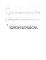
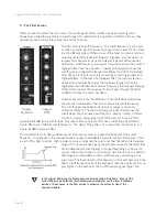
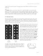
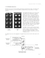
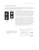
The Voyager has two voltage controlled filters (VCF’s) that can be configured either as dual lowpass filters 
or as a combination of highpass & lowpass through a front panel switch.  Additionally, the cutoff slope of 
each filter can be changed in software, resulting in a wide range of unique and interesting sounds.

Summary of Contents for Mini Voyager

Page 1: ...ard LH Controllers 37 I Touch Surface Controller 38 J Back Panel 39 K Interface Panel 41 THE USER INTERFACE Panel Mode 43 Edit Mode 49 Master Mode 63 How theVoyager handles MIDI 76 APPENDICES A Touch...

Page 2: ...and he s got this printed circuit board with some black goop on it his hands were covered in it and with that famous sly grin of his says to me Here it is So I asked him where he got it from and how...

Page 3: ...esis For those interested MIDI interface specifics see the section titled How the Voyager handles MIDI as well as Appendix D MIDI Implementation Those who are new to MIDI should first read MIDI Basics...

Page 4: ...ed AC outlet If you have theVoyager Rack Mount Edition RME you will also need 1 A MIDI controller or a computer with a MIDI interface and MIDI sequencing software 2 A MIDI cable for connection to the...

Page 5: ...witch RME Only If you are connecting theVoyager RME to an unbalanced input using 1 4 TS instrument cables such as an amplifier combo or a mixer s unbalanced inputs make sure the switch on the back of...

Page 6: ...l of 896 locations in memory for presets all are user programmable Note that once a preset is called up you can tweak the parameters to your liking using the front panel controls Any changes made to t...

Page 7: ...EL PARAM Press ENTER and you will see the prompt Load actual panel parameter Yes No Use the CURSOR to selectYes and press ENTER The sound produced by theVoyager is now determined by the settings of th...

Page 8: ...ng temperture range Using the RME as a Table top Unit TheVoyager Rack Mount Edition is designed so it can be used as a table top unit with the front panel tilted at an angle that is very convenient fo...

Page 9: ...r that is a descendant of the classic Minimoog Its sound sources are an external audio input a noise source and three analog variable waveform oscillators The Voyager has front panel controls for real...

Page 10: ...he Basics RME Front Panel The RME offers the same front panel controls asVoyager Keyboard Editions and is nearly identical in its layout save for theTouch Surface not offered on the RME and a repositi...

Page 11: ...puts are provided on 1 4 jacks A jack with a red nut indicates a CV Expression Pedal input while a jack with a blue nut indicates a gate footswitch input CV outputs are provided on a 25 pin ac cessory...

Page 12: ...This jack allows you to interrupt the signal routing between the Mixer and Filter to insert an external effect or take the output of the Mixer directly The Filter section is responsible for altering...

Page 13: ...e the other is controlled by the MOD1 CV which is a CV input on the back panel The MOD 1 CV input is normalled to 5V so with nothing plugged into this jack the PEDAL ON bus is on at the level determin...

Page 14: ...rface parameters X Y A Gate can also be programmed as modulation destinations through Edit Mode programming see Edit Mode 5 1 T S DESTINATIONS Digital Features TheVoyager has three operation modes Pan...

Page 15: ...current bank When the desired preset is reached pressing the ENTER button will load the new preset 3 TheVoyager responds to MIDI Bank Select and Program Change messages For storage and recall of more...

Page 16: ...und source in the Mixer has a dedicated ON OFF switch and a level control The audio output of the Mixer is routed to the Filter through an insert jack on theVoyager s back panel If an insert cable is...

Page 17: ...le jack as shown below The return signal is applied to the ring of the jack A cable fully plugged into the jack breaks the connection between the Mixer and the Filter and unless the Return signal is s...

Page 18: ...cillators are controlled by a number of sources The main source is the pitch CV generated by keyboard or by MIDI Note ONs A glide circuit can be switched in between the Keyboard CV and the oscillators...

Page 19: ...from the front panel individually for each oscillator modulation through the Mod Busses is applied to all three waveform controls simultaneously When using modulation it is possible to make the width...

Page 20: ...or as a modulation source LFO When the swicth is in the HI position Oscillator 3 operates with the same available frequency range as Oscillator 2 Related Oscillator Controls Two other panel controls...

Page 21: ...l the oscillator wave forms All three oscillators are effected by this connection The effective input range is 0 to 5V the result is dependant upon the panel WAVE control knob setting a positive CV wi...

Page 22: ...ines the minimum frequency that will pass through What s left is a band of frequencies that will pass through the filters unaffected hence the name bandpass Another key term is the Cutoff Slope The cu...

Page 23: ...ghpass Lowpass mode theVoyager s filters are configured as a lowpass and highpass filter in series resulting in a bandpass filter The output of the bandpass filter is routed to both outputs As with th...

Page 24: ...frequency that is one octave higher than the right filter This means when the CUTOFF control is swept two resonant peaks are heard giving the filter a unique quality In Highpass Lowpass mode the SPACI...

Page 25: ...e full level to the level set by the SUSTAIN control The envelope will remain at the Sustain level as long as an envelope gate signal is present i e a key is held down When the gate signal is released...

Page 26: ...envelopes are triggered by a gate signal The envelopes will sustain as long as a gate signal is present When the gate is off the Release portion of the envelope is executed as shown below The switch...

Page 27: ...GATE jack allows you to connect a footswitch or input a CV gate signal to remotely trigger both Envelope Generators This input triggers the EG s only when the front panel ENV GATE switch is set to ON...

Page 28: ...eadphones Additional CV Control applies to all Voyager keyboards and the RME with the VX 352 CV Input Expander only Volume The VOLUME jack allows you to connect an external CV or expression pedal to c...

Page 29: ...is the Modulation Wheel itself on the RME it s MIDI CC1 which is the default Mod Wheel CC message The performance control for the PEDAL ON Buss is the MOD 1 Input on theVoyager keyboard for the RME it...

Page 30: ...ough a combination of the SOURCE control and software modulation options The Source selections are the LFOTriangle wave the LFO Square wave OSC 3 Oscillator 3 S H the LFO Sample and Hold output ON MOD...

Page 31: ...MOUNT control is set to 0 no modulation will pass When the AMOUNT is set to 10 the maximum amount of modulation is sent to the destination when the performance controller Mod Wheel or MOD1 level is al...

Page 32: ...With an input applied when the voltage is at 0 no modulation is sent to the PEDAL ON Modulation Destination When theVoltage at the MOD1 is at 5Volts the Modulation is sent to the destina tion at the...

Page 33: ...appears at the output of the S H circuit is a random voltage that changes in time with the LFO TheVoyager s CV Interface jacks on the back panel of theVoyager keyboard or on the RME sVX 352 CV Expand...

Page 34: ...tart the LFO Additional CV Control applies to all Voyager keyboards and the RME with the VX 352 CV Input Expander only LFO Rate The LFO RATE jack accepts an expression pedal or a control voltage from...

Page 35: ...nal dimension to the sound As you explore the presets don t forget to try the Modulation Wheel to hear this added effect on the sound Glide The GLIDE switch turns the Glide function ON and OFF The gli...

Page 36: ...by the Touch Surface Controller can be routed two ways Destinations can be programmed using the Touch Surface Destinations selection in the EDIT mode menus There are 32 possible destinations that can...

Page 37: ...tput impedance of 600 In unbalanced mode the outputs are floating TRS connections Set the OUTPUT MODE switch to its proper position prior to power up and do not change its position while the RME is am...

Page 38: ...s that appear on the back panel of Voyager keyboards and allows the RME to be interfaced with other CV equipment For more on theVX 351 andVX 352 see Appendix G 1 You can use the Voyager to process any...

Page 39: ...aming and saving presets is done in EDIT mode MASTER Used for accessing global settings for theVoyager and data send and receive functions The LED s located above the PANEL EDIT and MASTER buttons wil...

Page 40: ...presets and global and is occasionally used as a navigation control in certain menus Cursor The CURSOR button is used to navigate the display and make menu selections 1 1 The 1 1 buttons are used to s...

Page 41: ...can be brought back through the RECALL function in Edit Mode Once the program number is changed the buffer is cleared Presets are stored in the Voyager s 896 memory locations These memory locations a...

Page 42: ...display returns to the preset name and number Choose NO and this function is off To make a change in the Parameter Display menu use the CURSOR to highlight the desired choice and press ENTER In PANEL...

Page 43: ...termined by the settings of the front panel controls To make a change in this menu use the CURSOR to highlight the desired choice and press ENTER GLIDE FUNCTION RME only This function works like the G...

Page 44: ...and press ENTER Bright Bass is one of 32 assignable sound categories For a complete list of all the categories as well as details on assigning sounds refer to Edit Mode section 6 2 SOUND CATEGORY REL...

Page 45: ...allows you to switch the Local Control of all three functions at once To change the status of any Local Control function use the CURSOR to make a selection and press the 1 1 buttons to select ON OFF W...

Page 46: ...RESET and press ENTER Use the cursor to move to the Preset field Press PANEL to go back to Panel mode Now when you press CURSOR the preset should show as being loaded into the Compare buffer It will r...

Page 47: ...ns that span six pages as shown below Voyager RME EDIT menus In addition to the functions shown above Edit Mode also features an octave transpose function that allows you to shift theVoyager s Keyboar...

Page 48: ...everts to the original saved settings If you want to get back to your edited sound press the EDIT button and select the RECALL LAST SOUND function Use the CURSOR to select YES and press ENTER You will...

Page 49: ...hen the desired interval is reached 2 1 PGM M WHL SOURCE Programmable Modulation Wheel Source PGM M WHL SOURCE that allows you to program one of 8 additional modulation sources to be used when the Mod...

Page 50: ...highlight the desired selection and press ENTER The available destinations are LFO Rate default Osc 1 Level Filter Resonance Osc 2 Level Filter Spacing Osc 3 Level Panorama Noise Level 3 1 PGM SHAPIN...

Page 51: ...h Bend Wheel Modulation Wheel Velocity Release Pressure AT Keyboard CV Touch Surface X Touch Surface Y Touch Surface A Mod1 Mod2 The Fixed Value parameter is an offset voltage that can be used by itse...

Page 52: ...the SPACING control In Dual Lowpass Mode Filter B appears on the LEFT output jack when both outputs are connected In Highpass Lowpass Mode Filter B is the Highpass filter Use the 1 1 buttons to select...

Page 53: ...on DEST There are 32 destinations for the Touch Surface outputs X Y and A Note that the X Y and A outputs are generated only when you make contact with theTouch Surface LFO Rate Glide Rate Mod Wheel M...

Page 54: ...axis does not modulate the destination 50 means that the amount of the touch surface output adds 50 of the total range of that control to its present value For example if the TSX destination is set t...

Page 55: ...H Gate Input connection on the VX 352 If nothing is connected to the S H Gate Input jack the sample rate of the TS LFO S H function is controlled by the RME s LFO 2 The Touch Surface sample is actuall...

Page 56: ...ls like Pitch Bend orVelocity or front panel controls like the LFO Rate control Each of the four mappings has it own dedicated menu Use the 1 1 buttons to select the desired map and then press ENTER A...

Page 57: ...utoff Filter Spacing Filter Resonance Filter KB Control Amount Filter Attack Filter Decay Filter Sustain Filter Release Filter Envelope Amount Volume Attack Volume Decay Volume Sustain Volume Release...

Page 58: ...the Filter Cutoff when the Pitch Bend wheel is increased Src Pitch Bend Dest Fil Cutoff Direction Normal Amount 25 Alternate suggestion Try the Filter Cutoff mapping above with Pitch Bend set to OFF s...

Page 59: ...Help Category menu in Panel Mode For more information refer to the HELP CATEGORY function in Panel Mode see page 46 6 3 PRESET NAME PRESET NAME allows the you to assign a name to a preset Preset names...

Page 60: ...For example if the last saved location is G009 the default EDIT memory location will be G009 as shown Note also that the name of the Preset that is stored at the specified memory location is always di...

Page 61: ...unctions that span five pages while the RME has a slightly different set of 16 Master Mode functions that span four pages as shown Voyager RME Voyager Keyboard In addition to selecting Master Mode pre...

Page 62: ...h Surface T S An eighth selection All allows you to switch the Local control of all seven functions at once To change the status of any Voyager control function use the CURSOR to make a selection and...

Page 63: ...e OFF messages from theVoyager s MIDI In jack to the MIDI Out jack When this function is disabled NO only MIDI events created by the instrument appear at the MIDI Out To change the setting use the CUR...

Page 64: ...is saved using SEND PRESET S the storage loca tion of that preset is also saved but with SEND PANEL SOUND it is not This means that if you select and save Preset 37 in SEND PRESET S that preset will...

Page 65: ...the Voyager will include this new value in the Device ID byte If that SysEx message is sent back to several Voyagers only the Voyager that has matching Device ID will receive the message all others wi...

Page 66: ...ual for more informa tion VELOCITY CURVE Keyboard editions only TheVELOCITY CURVE function allows you to tailor the velocity response to your playing style TheVoyager offers three velocity curves SOFT...

Page 67: ...69 Voyager User s Manual MASTER Mode Factory Setups AllVoyager editions keyboards and RME have the same Factory Setup menus which span four pages as shown TheVoyager Factory Setup Menus Factory Setup...

Page 68: ...end Preset s 3 3 Receive Presets SYSEX ENABLED 3 4 SysEx Device ID 1 4 1 Transpose In Out KYBD 0 MIDI 0 4 2 MIDI Key Order MAX 2 ACTIVE OFF 4 3 Velocity Curve NORMAL 4 4 Copyright Info 5 1 SoftwareVer...

Page 69: ...d Area axes as well as theTouch Surface Gate The default values are TS X Filter Cutoff MIDI CC Off Direction Normal Amount 50 TS Y Filter Spacing MIDI CC Off Direction Normal Amount 50 TS A Filter Res...

Page 70: ...the CURSOR to select YES and press ENTER To leave this menu without changes select NO and press ENTER 2 2 SHAPING 1 2 The SHAPING 1 2 function restores the default settings for the Programmable Mod Bu...

Page 71: ...e without changes select NO and press ENTER 3 4 PITCH BEND AMT The PITCH BEND AMOUNT function sets the Pitch UP and DOWN values to Fourths 5 semitones for all presets in the current bank To set the Pi...

Page 72: ...nsfer is complete theVoyager LCD will prompt you to transfer the next bank Bank C Enable your SysEx program again and then press ENTER When the transfer is complete the LCD will return to the Master M...

Page 73: ...System Exclusive SysEx data transfers to from the Voyager requires A computer with Internet access and a MIDI interface MIDI Software capable of sending a generic Sysex bank file syx or Standard MIDI...

Page 74: ...16 31 Square 32 47 Osc 3 48 63 S H 64 79 ON Mod2 80 127 Noise PGM MW DESTINATION Selects the Mod Wheel bus destination 69 0 15 Pitch 16 31 Osc 2 32 47 Osc 3 48 63 Filt 64 79 Wave 80 127 LFO Rate PGM...

Page 75: ...SC 2 FREQ Adjusts the frequency of oscillator 2 10 MSB 42 LSB OSC 2 OCTAVE Sets the octave of oscillator 2 75 0 15 32 16 31 16 32 47 8 48 63 4 64 79 2 80 127 1 OSC 2 WAVE Sets the waveform of oscillat...

Page 76: ...AMOUNT Adjusts the amount of pitch CV affecting the cutoff 22 MSB 54 LSB MODE Toggles the filter mode between LP LP and HP LP 86 0 63 OFF 64 127 ON Envelope Generator FILTER ENV ATTACK Adjusts the fil...

Page 77: ...ion When theTS LFO S H is switched ON for TSX TSY orTSA it effects all of the assignable control parameters for that axis including the Destination MIDI Control Number 1 127 Direction Normal or Invert...

Page 78: ...types of messages into channel messages and system messages Channel Messages are for things like Note Ons and other performance information while System Messages include System Exclusive commands and...

Page 79: ...he table on page 71 for a list of CCs used for theVoyager s parameters PROGRAM CHANGE A message that tells the receiving device synthesizer tone generator drum machine etc which preset or patch progra...

Page 80: ...just explore the various param eters to see what they do The following tables list the complete default values of the Initialization Preset Front Panel Controls SECTION PARAMETER VALUE Mixer EXTERNAL...

Page 81: ...CTION PARAMETER VALUE Pot Mapping MAP 1 SOURCE VELOCITY ATTACK MAP 1 DEST MASTER VOLUME MAP 1 DIRECTION NORMAL MAP 1 AMOUNT OFF MAP 2 SOURCE KEY PITCH MAP 2 DEST FILTER RESONANCE MAP 2 DIRECTION INVER...

Page 82: ...ematically related overtones of the base pitch To explain what that means let s consid er an example if the base pitch is 100 Hz harmonics will occur at 200 Hz 2 x 100 300 Hz 3 x 100 400 Hz 4 x 100 et...

Page 83: ...e richest sounding of the four waves It contains all of the harmonics and has a bright buzzy sound Sawtooth waves are ideal for brass and string sounds bass sounds and rich accompaniments The square w...

Page 84: ...ilters commonly have several adjustable parameters to allow you to modify and shape the sound these are called Cutoff and Resonance The Cutoff is the point at which the filter begins to remove frequen...

Page 85: ...the maximum voltage the fade in time Decay The time to go from the maximum voltage to the Sustain level Sustain The maximum level of the envelope after completing the Attack and Decay stages if the k...

Page 86: ...dd some solid programming and playing technique and incredibly expressive musical sounds can be achieved So what is the best way to program synthesizers effectively The answer to that question could f...

Page 87: ...Note OFF data is transmitted from theVoyager keyboard version only After touch X X Aftertouch data is transmitted from theVoyager keyboard version only Pitch Bend O O Pitch Bend data is transmitted fr...

Page 88: ...ed we will examine the product for any obvious signs of user abuse or damage as a result of transport If the product has been abused damaged in transit or is out of warranty we will contact you with a...

Page 89: ...ght of the keyboard By running the lamp at half intensity the useful life of the lamps may easily extend beyond 10 000 hours or more When full counter clockwise the lamp is turned off We recommend tur...

Page 90: ...r size and weight the synth can actually be carried to gigs without having to rely on a road crew Finally a serious synthesizer made for the working musician Flash forward to today The MinimoogVoyager...

Page 91: ...nector on theVX 352 labeled FROM ACCESSORY PORT Now let s start with a basic sound and see how theVX 351 andVX 352 can work with theVoyager Power up theVoyager keyboard or RME Press the EDIT button In...

Page 92: ...e used for determining the pitch of theVoyager sVoltage Controlled Oscillators VEL This is the CV determined by the velocity used to depress a key PRESS This is the CV determined by how much pressure...

Page 93: ...put of theVolume Envelope Generator S H This group of outputs is generated by the Sample and Hold Circuit STEP This is the output of the Sample and Hold Circuit SMOOTH This is the Smoothed output of t...

Page 94: ...V Nominal ENVS FILTER 0 5V VOLUME 0 5V S H STEP 2 to 2V Nominal SMOOTH 2 to 2V Nominal Noise Noise 1V Nominal The table below shows the effective ranges of theVX 351 Outputs Note 1 The voltages shown...

Page 95: ...t a footswitch or input a CV gate signal to remotely trigger both Envelope Generators This input triggers the EG s only when the front panel ENV GATE switch is set to ON EXT If the ENV GATE switch is...

Page 96: ...nization of theVoyager s LFO The LFO SYNC jack accepts a footswitch or a 5V Gate input Closing the footswitch or applying a gate retriggers the LFO waveform MOD This group of inputs allows you apply e...

Page 97: ...passes to the output The OFFSET control allows you to add an offset voltage to the output signal up to 5V but the total combined output voltage Input plus Offset will not exceed 7 5V MULT TheVX 352 co...

Page 98: ...e table below shows the effective ranges of theVX 352 Inputs All non gate inputs supply power allowing you to connect either an expression pedal or a control voltage Note 1 The voltage range shown cov...

Page 99: ...One thing to keep in mind is that although theVoyager can remember the settings of the front panel controls as a preset it cannot save the routings of patch cables or the positions of the attenuators...

Page 100: ...buss signal modulates more than one destination This is a way to use one Modulation signal to control more than one destination Initialize theVoyager s parameters Using a patch cord connect the Mod W...

Page 101: ...output to theVoyager s Envelope Gate ENV GATE Input Switch the front panel ENVELOPE GATE switch to ON EXTERNAL You should immediately hear a note repeating at the LFO rate 5 Using the Mults Here is a...

Page 102: ...ete the modulation routing To createVibrato Using a patch cord connect the CP 251 Attenuator Output to theVoyager s PITCH jack or the OSC PITCH jack on theVX 352 On the CP 251 set the LFO RATE control...

Page 103: ...Hold staircase patterns A Sample and Hold circuit can be used for more than generating random voltages One type of modulation pattern that can be achieved is called Staircase modulation It is achieve...

Page 104: ...control toTriangle wave Set the FILTER ENVELOPE controls to the following settings ATTACK 1 msec DECAY 100 msec SUSTAIN 0 RELEASE 0 Using a patch cable connect theVX 351 Filter Envelope output ENVS FI...

Page 105: ...MF 103 12 Stage Phaser Use theVoyager s Mod Wheel to control the Mix on the MF 102 Ring Modulator Use theVoyager sTouch Surface to control the MF 102 s Carrier Oscillator Frequency Use theVoyager s No...

Page 106: ...reset Edit and Master function buttons Selection Navigation Controls Cursor Enter and 1 1 buttons Backlight Variable intensity illumination of theVoyager panel with a dedicated Brightness control Back...

Page 107: ...e cable allowing the RME to accept external control signals on standard 1 4 interface jacks With both theVX 352 theVX 351 CV Expanders the RME becomes a semi modular synthesizer CP 251 ControlVoltage...

Page 108: ...tions and is custom fitted to theVoyager With rugged heavy duty recessed wheels and an internal compartment large enough for storing cables and our new EP2 Expression Pedal this case stands up to the...

Page 109: ...e contour We also hear the frequency of the sound go slightly higher when the string is plucked and then drop slightly as the note fades This is the pitch envelope contour A synthesizer can create the...

Page 110: ...the carrier The carrier oscillator is the one you hear When the modulator frequency is very low about 6Hz the effect is described as vibrato As the modulator frequency is raised into the audio range...

Page 111: ...ager has three oscillators for generating sounds Pitch The subjective perception of sound A bass guitar generates low pitches while a flute generates high pitches Pole or poles A term referring to the...

Page 112: ...here the gain is a function of the control voltage In theVoyager theVCA is paired with theVolume Envelope Generator to specify the articulation of a sound Another CV source for theVCA in theVoyager is...

Page 113: ...esigned for theVoyager Rack Mount Edition Contributors Nigel Hopkins Brian Kehew Will Alexander and Moog Music Bank C designed for theVoyager Electric Blue Edition Contributors Bernie Worrell Drew New...

Page 114: ...GETTING MEAN Solar 32 Rezzy Fifths Grits and Eggs Bass Purple Jude SYNCROWL Here it comes GETTING MEAN AGAIN Troll 33 Glassy Mod Sparkle Jan 7 Days Deep Space Tones CUTIE PIE BASS Panning Throbber WIR...

Page 115: ...96 Cluster Drum Yc45 RM Pulsing Bass PUSH CLOSEDLIFT OPEN Wrong Crypt VULGAR BASS Preset Default PROG 97 Skinny Keys Pre Mental Tension Water Wheels MY FLOWBEE Just the harmonics HIP AND HOP Preset D...

Page 116: ...MinimoogVoyager User s Manual Moog Music 2008 all rights reserved Text and illustrations by Greg Kist Steve Dunnington and the resources of Moog Music...

Reviews: