background image

16

17

ABOUT ANALOG DELAYS

A delay circuit produces a replica of an audio signal a short time after the 
original signal is received. If you listen to the original (direct) signal and the 
delayed signal together, the delayed signal will sound like an echo of the 
direct. To make a whole series of echoes that die out gradually, you feed 
the delayed output signal back to the input. You can determine how far 
apart the echoes are by adjusting the delay time of the delay circuit, and 
you can adjust how fast the echoes die out by adjusting the amount of 
feedback from the delay. In addition, you can determine how loud echoes 
are by adjusting the mix between the direct signal and the delayed signal. 

During the early 1970s, large-scale semiconductor analog delay circuits 
came into being. These are called Bucket Brigade Delay (BBD) chips, 
because they function by passing the audio waveform down a chain of 
several thousand circuit cells, which is analagous to water being passed by 
a bucket brigade to put out a fire. Each cell in the chip introduces a tiny 
delay. The total time delay depends on the number of cells and on how 
fast the waveform is “clocked”, or moved from one cell to the next.

In the MF-104M, the LFO creates a control voltage that is used to modulate 
the time function of the delay. The BBDs in the Delay Line contain 8192 
“buckets”. With the time unmodulated the signal spends the same amount 
of time in each bucket based on the selected delay time. With the time 
modulated by the LFO, the time is no longer constant (or static) and audio 
signals already in the buckets get time compressed or stretched. A good 
analogy for picturing this is a clock with a sweep hand to show the seconds.  
Imagine that you could hold the sweep hand and either slow it down or 
speed it up. Yet, when you let it go the sweep hand instantly went to the 
correct position on the clock face.  In a sense, this is how the LFO 
modulates the Delay Line.

In an analog delay the input can be set to saturate gradually, limiting the 
maximum signal level and introducing some low level distortion.  This actually 
enhances the sound quality over what you would have if the MF-104M 
produced no distortion whatsoever.  

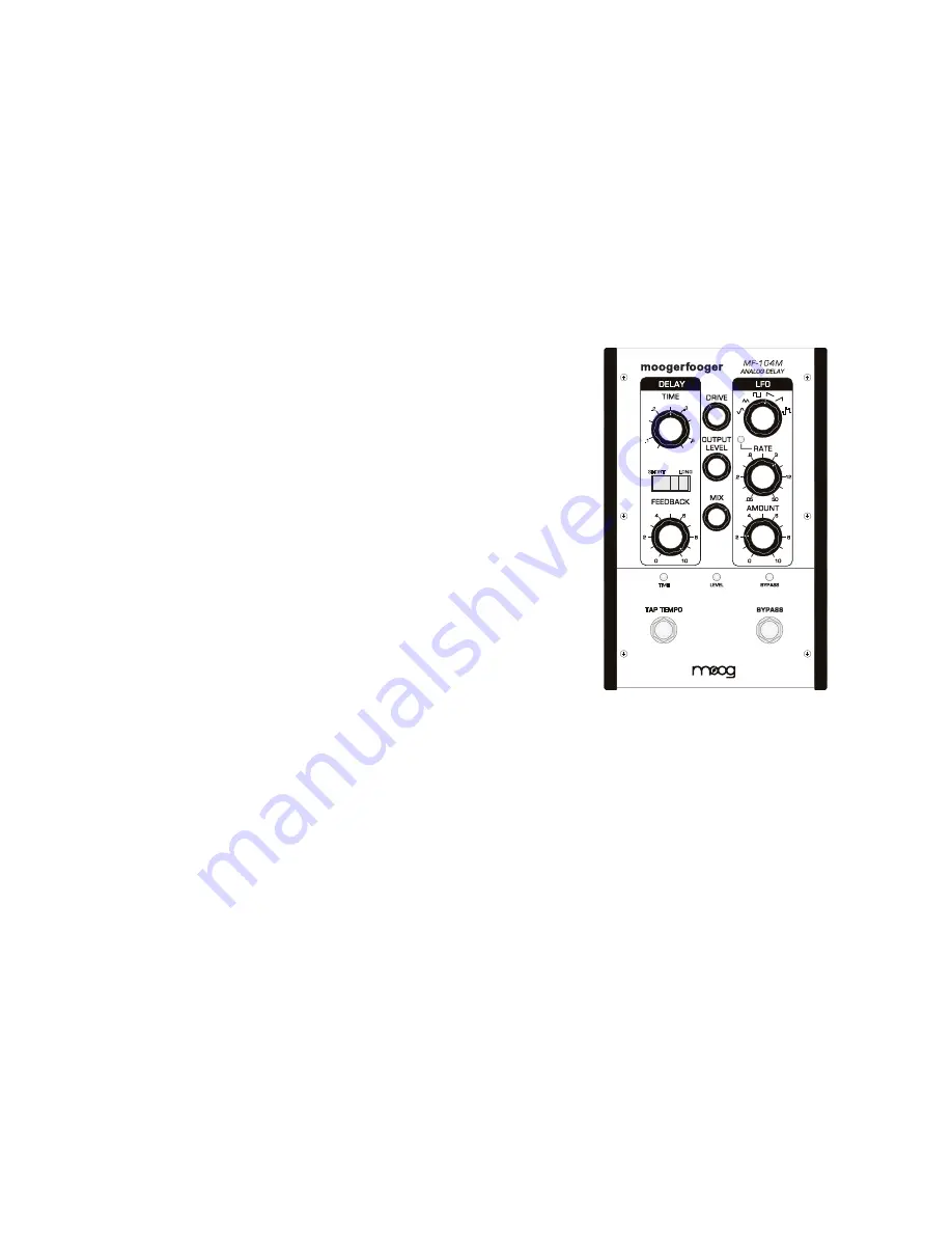
THE MF-104M FRONT PANEL

This section provides more in-depth descriptions of the controls and 
indicators on the MF-104M front panel.

MF-104M

ANALOG DELAY

TAP TEMPO

TIME

SHORT

LONG

.2

.1

.6

.3

DRIVE CONTROL -

 Sets the input sensitivity of the Analog Delay. This 

control is only active when the effect is 

ON

 or in 

SPILLOVER

 mode. The 

available gain runs approximately 35dB. The Analog Delay is designed to 
work with instrument to line-level signals. 

LEVEL LED -

 Works in conjunction with the 

DRIVE

 control. Red indicates 

clipping. Orange flashes indicate the start of overload. Green indicates the 
presence of signal at or below the nominal level.

NOTE: For most instruments, the best approach is to set the 

DRIVE

 level so the 

LEVEL 

LED

 stays consistently green with only peaks in the orange. It is okay to drive the Ana-

log Delay into clipping/distortion if that sound is desired. When using an instrument 
with a wide dynamic range, you may want to insert a compressor or limiter prior to 
the input of the Analog Delay for the best signal-to-noise ratio without clipping.


Summary of Contents for MF-104

Page 1: ......

Page 2: ...rporates a dual range Bucket Brigade Device BBD providing a range of delay times from 40 milliseconds to 800 milliseconds A multi waveform Low Frequency Oscillator LFO enables you to create a variety of effects including chorus pitch shifting and vibrato by modulating the Delay Line Several of the performance parameters are voltage controllable This means you can use expression pedals like the Moo...

Page 3: ...now about an update is by registering The easiest way is by visiting www moogmusic com register Connecting 1 Connect an instrument cable from your sound source to the AUDIO IN jack on your MF 104M You can feed virtually any instrument or line level signal through your MF 104M 2 If you plan on using MIDI connect a MIDI cable from the out on the MIDI controller of your choice to the MF 104M s MIDI I...

Page 4: ...infinite NOTE Feedback settings above 8 can cause the unit to self oscillate LEVEL CONTROLS CENTER PANEL DRIVE Allows 35 dB of adjustment of the input signal for optimum signal path level matching and overdriving sound sources OUTPUT Allows gain and attenuation of output signal for compatibility with a wide range of input devices MIX Crossfader control for blending wet and dry signals to the outpu...

Page 5: ...nt gratification skip to page 13 for some great setups GETTING TO KNOW THE DELAY LINE As you go through this section adjust controls as shown in the illustrations on the right side of the page to hear how dif ferent Delay Line settings affect the audio output Adjust the Delay Line settings as shown in Figure 4 then play your instrument That s the classic slapback echo Now increase the FEEDBACK con...

Page 6: ...BYPASS switch to turn the effect off while continuing to play The signal from your instrument will not be sent through the effect but any audio currently in the circuit will continue to sound as if the effect were on Pressing and holding the BYPASS button for two seconds toggles your Analog Delay between modes In NORMAL mode turning the effect OFF shuts off audio from the Delay Line Any new signal...

Page 7: ...moothly transitions from peak to trough with no harmonics Creates vibrato and tremolo effects when used to modulate another signal Triangle A periodic wave creates a triangle shape in moving from peak to trough Creates similar effects to a sine wave when modulating another signal but with a sharper tone due to the generation of odd harmonics Square A wave that alternates almost instantaneously bet...

Page 8: ...r the LFO RATE To set a tempo simply tap the switch at the desired tempo in quarter notes After the third tap the MF 104M will start calculating the tempo and keep the average tempo as you continue to tap To start over wait five seconds and then press the TEMPO switch three times to set a new tempo To revert to using the front panel control turn either the TIME knob or LFO RATE knob depending on w...

Page 9: ...tant or static and audio signals already in the buckets get time compressed or stretched A good analogy for picturing this is a clock with a sweep hand to show the seconds Imagine that you could hold the sweep hand and either slow it down or speed it up Yet when you let it go the sweep hand instantly went to the correct position on the clock face In a sense this is how the LFO modulates the Delay ...

Page 10: ...e effect is on or in Spillover mode The OUTPUT LEVEL control is designed so that an overall boost attenuation or zero gain state can be achieved with any DRIVE setting MIX Sets the ratio of dry signal as input to wet effected signal This control is only active when the effect is on Set fully counterclockwise it allows only the dry signal to pass to the MIX output The full clockwise position allows...

Page 11: ... supply to avoid damage to the device Make sure your power supply has the correct Input voltage specifications for your country 120VAC 60 Hz for the US and Canada 230VAC 50 Hz for Europe and South America The output of the adapter is 9VDC and the adapter should be capable of supplying a minimum of 400mA The 9VDC is applied to the tip center of a barrel connector plug w 5 5mm outer diameter and 2 1...

Page 12: ...he front panel controls When the corresponding front panel control is changed after receiving a MIDI CC message the value will return to that panel control MSB LSB refers to 14 bit MIDI which uses a pair of CC messages to obtain higher resolution control Use the MSB CC numbers to control these parameters at 7 bit resolution Note Moving a panel control while receiving MIDI CC messages for that same...

Page 13: ...ring terminals are supplied with 5 volts which is current limited The tip terminals receive the variable voltages from the pedals An expression pedal for use with the MF 104M should contain a 50K Ohm or lower linear taper potentiometer Applying a varying voltage to a pedal control input jack has the same effect as turning the corresponding knob With the panel controls set to mid position a voltage...

Page 14: ... REPLACEMENT REPAIR You must obtain prior approval and an RMA number from Moog Music before returning any product to us Wrap your MF 104M carefully and pack it with the power adapter in its original carton The warranty will not be honored if the product is not properly packed Send it to Moog Music with transpor tation and insurance charges paid A reasonable cost for service materials and return fr...

Page 15: ...ubject to change without notice Moog and Moogerfooger are registered trademarks of Moog Music Inc 2012 Moog Music Inc MOOG MUSIC INC 160 Broadway St Asheville NC 28801 P 828 251 0090 E info moogmusic com W www moogmusic com ...

Reviews: