Programmable Multi-Axis Servo Drive Power Supply Unit Operation Manual
ID no.: CA97556-001 Date: 03/2015
moog
64
Diagnostics
5
Diagnostics
5.1
Device states
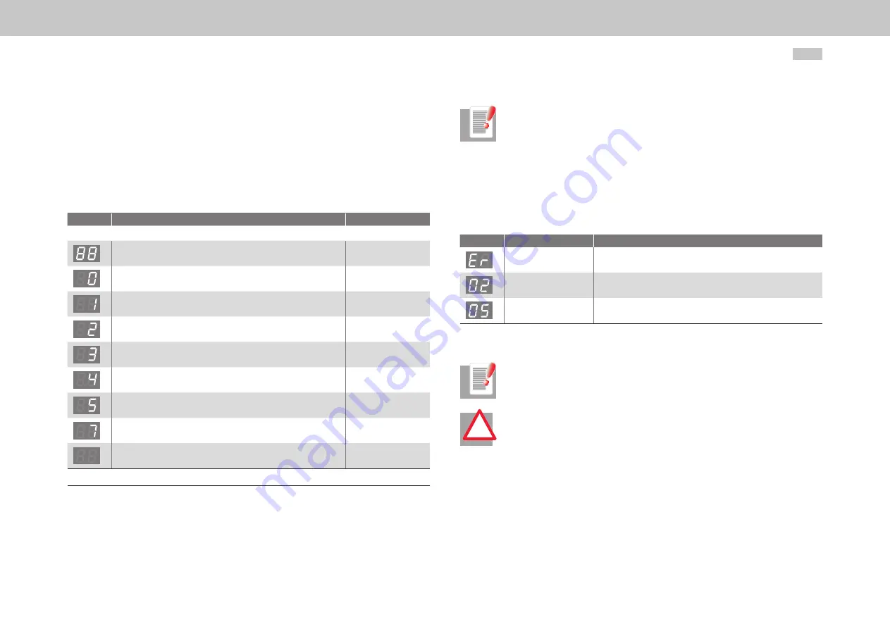
The device states can be read from the 7-segment display (D1, D2).
Display
Meaning
Parameter
System states
Device in reset state
Self-initialisation on device start up
(Start)
1)
Not ready (no DC link voltage)
(NotReady-
ToSwitchOn)
1)
Starting lockout (ENPO not set)(DC link precharged to ideal voltage,
power stage not ready)
(SwitchOnDisabled)
READY (ENPO set)(power stage ready)
(ReadyToSwitchOn)
On (DC link voltage is increased to reference setpoint / soft-start
active)
(SwitchedOn)
Power Supply Unit ready (DC link voltage setpoint reached)
(OperationEnabled)
Error reaction active
(FaultReactionActiv)
Error (for error list see section 5.2, p. 65)
(Fault)
1) Not a “Safe” display under the terms of IEC/EN 61800-5-2.
Table 5.1 Device states
NOTE:
The STO (Safe Torque Off) safety function is not required for the Power Supply
Unit, as no motors are connected. In order to start the Power Supply Unit, a
jumper must be placed between X4/14 and X4/22. If this jumper is forgotten,
the fact is indicated by a flashing dot on the device display. The STO safety
function is used in conjunction with a Multi-Axis Servo Drive.
5.1.1
Error
In event of error alternating display: ER > 02 > 05 * ER > 02 > 05 ...
Display
Meaning
Explanation
Error
ER = Error
Error name:
02 = Error in parameter list
Description of error:
05 = Function to check current parameter list
Table 5.2 Display in case of error
NOTE:
Errors can be reset in accordance with their programmed reaction (ER) or only
via a 24 V reset (X9/10) (ER.).
ATTENTION!
Errors marked with a dot can only be reset when the cause of the fault has
been eliminated.
!


