


3.3 Wiring
The use of crimp “boot lace ferrules” is recommended for the
screw terminals. Allow sufficient cable length so the circuit
card can be withdrawn from its case with the wires still
connected. This enables switch changes on the circuit card
to be made while the card is still connected and operating.
An extra 100mm, for cables going outside the enclosure,
as well as wires connecting to adjacent DIN rail units,
is adequate.
The screw terminals will accommodate wire sizes from 0.2mm
2
to 2.5mm
2
(24AWG to 12AWG). One Amp rated, 0.2mm
2
should be adequate for all applications.
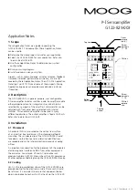
cable gland
100mm Loop
Wires
Enclosure
Radial screen
termination
Cable
Grounded EMI
Preferred Wiring
Page 2 of 6: C70916 Rev B – 4.10
Cable gland
100mm Loop
Cable
Enclosure
Cable
Wire soldered
to screen
Drain wire.
or
(Heat shrink to
cover the screen)
Alternative Wiring
3.4 EMC
The G122-829-003 emits radiation well below the level called
for in its CE mark test. Therefore, no special precautions are
required for suppression of emissions. However, immunity from
external interfering radiation is dependent on careful wiring
techniques. The accepted method is to use screened cables for
all connections and to radially terminate the cable screens, in
an appropriate grounded cable gland, at the point of entry into
the industrial steel enclosure. If this is not possible, chassis
ground screw terminals are provided on the G122-829-003.
Exposed wires should be kept to a minimum length. Connect
the screens at both ends of the cable to chassis ground.
4 Power supply
24V DC nominal, 22 to 28V
75mA @ 24V without a load, 200mA @ 100mA load.
If an unregulated supply is used the bottom of the ripple
waveform is not to fall below 22V.
It is recommended that an M205, 250mA T (slow blow) fuse,
compliant with IEC127-2 sheet 3, be placed in series with the
+24V input to protect the electronic circuit. If terminal 23 is
used to power a proportional valve, the fuse should be
increased to cater for the extra current.
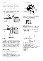
R17
1
2
3
4
spare
enable
dither
4-20mA (feedback input)
P gain range
Input 3 to
output amp
lim
cmd lag
feedback lead
Input 2 to
error amp
R34
R33
R16
SW5
SW4
SW 6
1
2
3
4
spare
PR
INT
E or P
SW5 V or
SW 3
Step P.B.
[SW1]
To access the circuit card switches, the circuit card must be
withdrawn from the case. See paragraph 17.
5 Set-up adjustments
Trimpots are all 15 turns.
Plug-in resistors are all “quarter watt” 1% metal film. Two
suitable types are Beyschlag MBB0207 and Roderstein
MK20207.
The amplifier is shipped in the following default state.
top board switches
SW3
STEP
not applicable
SW4
1
P-E
E
2
CMD LAG
off
SW5
IN 2
V
SW6
1
spare
off
2
PR
on
3
I
Lim
off
4
INT
off
bottom board switch, shown as [ ]
[SW1]
1
spare
off
2
ENABLE
on
3
DITHER
off
4
4-20mA (fdbk)
on
R17: 100k (P gain range 1 to 20)
R34: 100k (input 2 to error amp)
R33: not fitted (input 3 to output amp)
R16: not fitted (feedback derivative)
Feedback gain and zero pots: configured for 4-20mA input
Dither level pot: fully counter clockwise (FCCW)
Scale pot: FCCW
P gain pot: FCCW
I
gain pot: FCCW
Bias pot: 0V
ON
shown in on position
shown in off position
SW1 and 6 switch positions


