


903-0628-00 Rev. 1
Model 903-HD User's Guide – FMB-X-2.5
Focal Technologies Corp.
Page 4-26
For real-time control systems, average bus loads above 30% are not recommended due to the
non-linear increase in latency inherent with contention based protocols. For non-critical applications,
average bus loads should be kept below 50% to maintain good performance.
LEDs on the AIB-CANBUS card may be used for diagnostics during bench testing. Diode D3 is on when
power is applied to the card. Link LEDs D1 and D2 are both on when the optical link is established and off if
the optical link is not working. Link LEDs also indicate traffic on the local CAN bus: the green TX LED (D2)
flashes when there are frames going out to the local CAN bus; the red RX LED (D1) flashes when there are
frames being received from the local CAN bus. Error LED D4 is on for roughly half a second when a local
CAN frame error is detected and flashes when multiple errors are detected. LEDs D1, D2, and D4 are only
active in bridge mode. Note that the LEDs flash five times on power up to indicate the card is ready for
operation.
When the cards are configured in “Bridge Mode”, optical frames received with errors are dropped at the
receiving AIB and flagged by the error LED. Excessive optical link errors force the CAN port into reset until a
good optical link is re-established. On firmware revision A, a local CAN error or packet collisions forces a five
second reset of the CAN ports at both ends; firmware version B does not force a CAN reset, so other
methods must be used to convey detection of remote errors.
An on-board 120 ohm CAN terminator shown Figure 4-17 is for bench testing only (shunt across J11 pins 1-2)
and is normally left open (shunt across J11 pins 2-3). In typical industrial CAN networks operating with 12 or
24 VDC power, an external terminator should be used with sufficient power rating to handle a short to these
voltage rails and ground under worst-case conditions. (A 5W, 120-ohm terminating resistor is needed for 24
VDC systems.) Regardless, each CAN bus end node should be terminated with 120 ohms to ensure a net
bus load of 60 ohms.
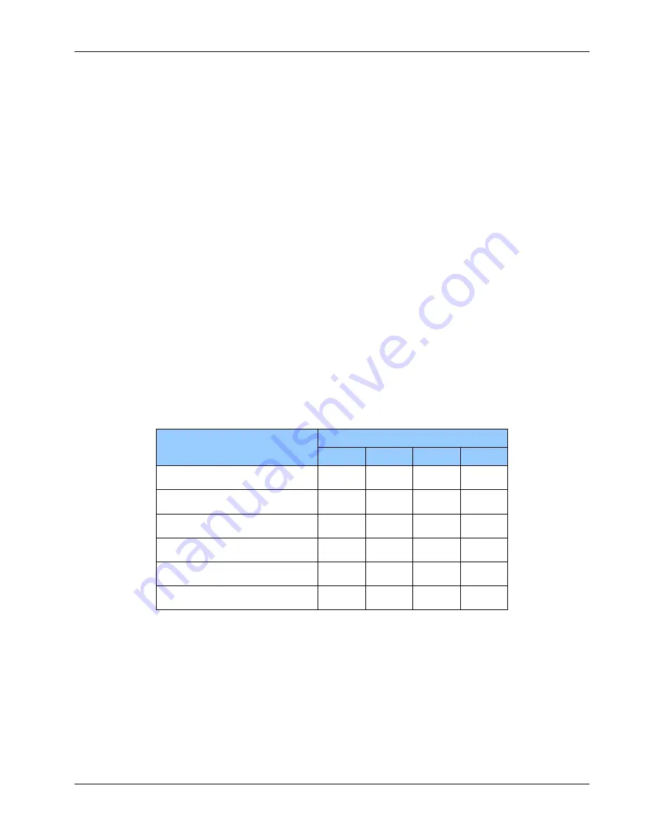
Switch SW1 on the AIB-CANBUS card may be used to set the optical link bit rate of the cards, indicated in the
table below. Remote and console cards must have the same settings.
Table 4-14: CAN Speed Settings
Speed
SW1 Settings
1
2
3
4
62.5kbps BRIDGE MODE
OFF
OFF
OFF
ON
125kbps BRIDGE MODE
OFF
OFF
ON
ON
250kbps BRIDGE MODE
OFF
ON
OFF
ON
500kbps BRIDGE MODE*
OFF
ON
ON
ON
1000kbps BRIDGE MODE*
ON
X
X
ON
REPEATER MODE (62.5kbps)
X
X
X
OFF
X = DON'T CARE
ON = 1 = CLOSED, OFF = 0 = OPEN
*Requires high speed data slot in Model 903 with medium or high speed backplane.
A slow (62.5 kbps) repeater mode is available in which the bridge mode is disabled and the optical link simply
maintains a direct “virtual wired connection” between the paired AIB-CANBUS CAN ports. This provides
extremely low latency, typically less than 4 us, but can only be used with short fiber links and is not
recommended for ROV configurations. LEDs D1, D2, and D4 are disabled in this mode.
Summary of Contents for Focal 903
Page 78: ...903 0628 00 Rev 1 Model 903 HD User s Guide FMB X 2 5 This page intentionally left blank ...
Page 79: ...903 0628 00 Rev 1 Model 903 HD User s Guide FMB X 2 5 APPENDICES ...
Page 80: ...903 0628 00 Rev 1 Model 903 HD User s Guide FMB X 2 5 This page intentionally left blank ...
Page 86: ...903 0628 00 Rev 1 Model 903 HD User s Guide FMB X 2 5 This page intentionally left blank ...
Page 89: ...903 0628 00 Rev 1 Model 903 HD User s Guide FMB X 2 5 APPENDIX E BACKPLANE PIN CONFIGURATIONS ...