DISASSEMBLY
1. Loosen jam nut, washer (3700/7500) and thread seal. Screw adjustor out of cylinder
head. Remove thread seal, washer (3700/7500) and jam nut.
2. Thoroughly clean and inspect all parts for wear or damage. Replace with new parts
as required.
RE-ASSEMBLY
NOTE:
MUST BE RE-ASSEMBLED BEFORE CYLINDER HEAD IS MOUNTED TO
CYLINDER TUBE.
1. Install jam nut, washer (3700/7500) and thread seal on adjustor.
2. Screw adjustor into the cylinder head. Thread into head until adjustor is flush with
the inside of the cylinder head (Approx. 6-7 turns).
3. Adjust rotation at test. Turning adjustor clockwise reduces rotation, counter-
clockwise increases rotation.
NOTE:
ADJUSTMENTS SHOULD NOT BE MADE WHILE UNIT IS UNDER PRESSURE. FOR
DUAL RACK UNITS, BOTH ADJUSTORS AT EACH END OF STROKE MUST BE SET
EQUALLY SO END OF STROKE LOAD IS EQUALLY ABSORBED BY (2) CYLINDER
HEADS.
DISASSEMBLY
1. Remove cover screw and cover screw seal.
2. Loosen the adjustable stop-set screw.
3. With cylinder head removed from cylinder tube, the adjustor can be removed by
screwing out towards the inside of the cylinder head with a hex wrench
4. Remove nylon pellet and inspect for wear and damage. Replace with new pellet
if required.
RE-ASSEMBLY
NOTE:
MUST BE RE-ASSEMBLED BEFORE CYLINDER HEAD IS MOUNTED TO
CYLINDER TUBE.
1. Screw adjustor into cylinder head from inside cylinder head face. Screw adjustor in
until flush or below the surface of the cylinder head so rotation can be adjusted
at test.
2. Install nylon pellet and set screw but do not tighten until adjustment is set.
3. Adjust rotation at test. Turning adjustor clockwise reduces rotation, counter-
clockwise increases rotation.
NOTE:
ADJUSTMENTS SHOULD NOT BE MADE WHILE UNIT IS UNDER PRESSURE.
FOR DUAL RACK UNITS, BOTH ADJUSTORS AT EACH END OF STROKE MUST
BE SET EQUALLY SO END OF STROKE LOAD IS EQUALLY ABSORBED BY (2)
CYLINDER HEADS.
4. When adjustment is complete, tighten set screw to lock position.
5. Install cover screw seal and cover screw.
DISASSEMBLY
NOTE:
CYLINDER HEAD MUST BE REMOVED FROM THE CYLINDER TUBE
BEFORE DISASSEMBLY.
1. Remove jam nut.
2. Screw adjustor out of the cylinder head. Remove O-ring and back-up ring from
adjustor head.
3. Thoroughly clean and inspect all parts for wear or damage. Replace with new parts
as required.
RE-ASSEMBLY
NOTE:
MUST BE RE-ASSEMBLED BEFORE CYLINDER HEAD IS MOUNTED TO
CYLINDER TUBE.
1. Install new back-up ring and O-ring on adjustor head making sure the flat of the
back-up ring is on the cylinder head side of the seal groove and the curved side is
toward the O-ring and cylinder tube side. Make sure the O-ring is installed in the
curved portion of the back-up ring.
2. Screw adjustor into the cylinder head from inside of the cylinder head. Screw
adjustor all the way in so rotation can be adjusted at test.
3. Adjust rotation at test. Turning adjustor clockwise reduces rotation, counter-
clockwise increases rotation.
4. Tighten jam nut.
NOTE:
ADJUSTMENTS SHOULD NOT BE MADE WHILE UNIT IS UNDER PRESSURE.
FOR DUAL RACK UNITS, BOTH ADJUSTORS AT EACH END OF STROKE MUST
BE SET EQUALLY SO END OF STROKE LOAD IS EQUALLY ABSORBED BY (2)
CYLINDER HEADS.
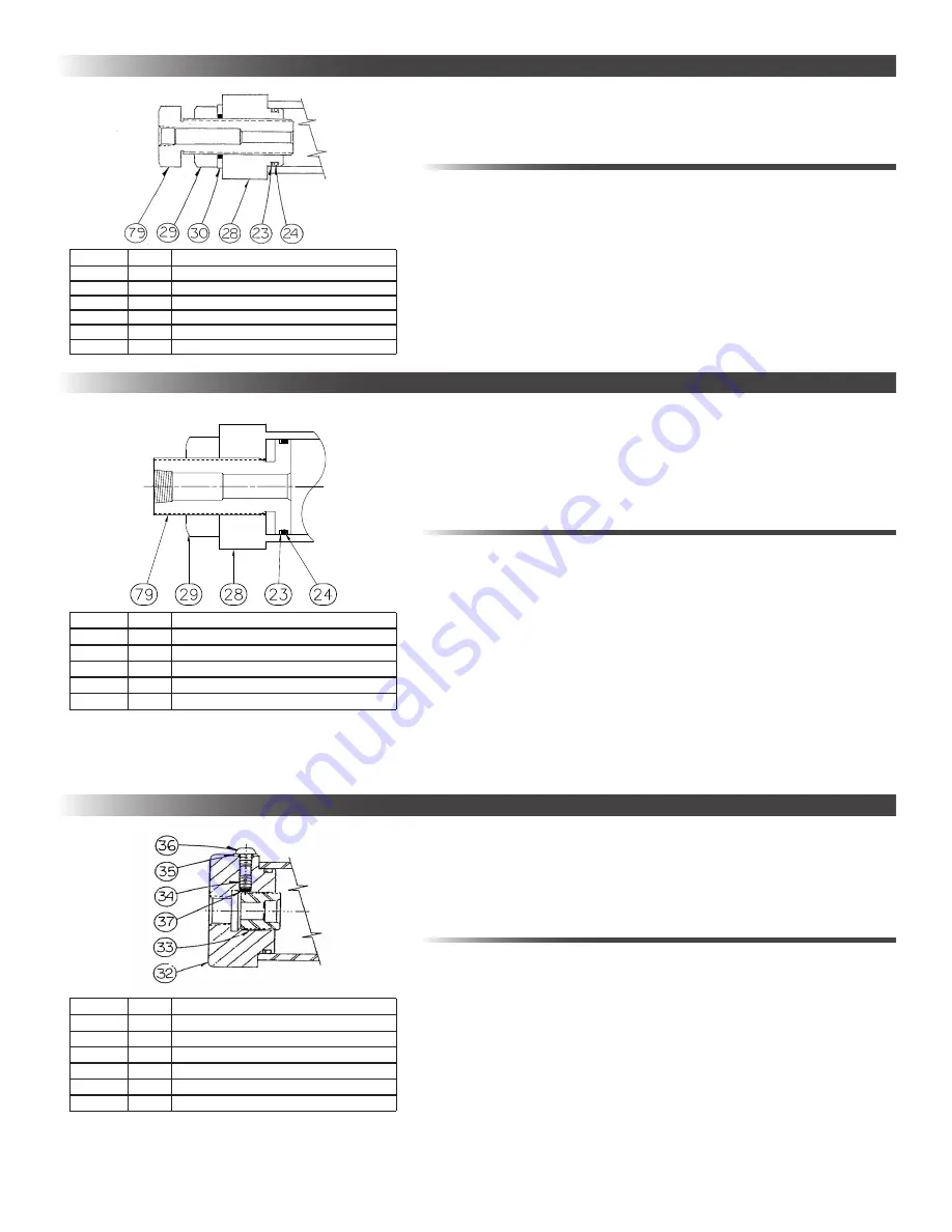
0° TO 30° EXTERNAL ADJUSTABLE STOPS (MODELS 900-7500)
0° TO 5° INTERNAL ADJUSTABLE STOPS (MODELS 3700-30,000)
0° TO 30° EXTERNAL ADJUSTABLE STOPS (MODELS 15,000 & 30,000)
ITEM
QTY
PART NAME
23
1
BACK-UP RING
24
1
O-RING
28
1
EXTERNAL ADJUSTOR, CYLINDER HEAD
29
1
JAM NUT
30
1
THREAD SEAL
79
1
EXTERNAL ADJUSTOR, FIXED CUSHION
ITEM
QTY
PART NAME
32
1
CYLINDER HEAD
33
1
0
O
TO 5
O
INTERNAL ADJUSTABLE STOP
34
1
SET SCREW - ADJUSTABLE STOP
35
1
THREAD SEAL - COVER SCREW
36
1
COVER SCREW
37
1
NYLON LOCKING PELLET
ITEM
QTY
PART NAME
23
1
BACK-UP RING
24
1
O-RING
28
1
EXTERNAL ADJUSTOR, CYLINDER HEAD
29
1
JAM NUT
79
1
EXTERNAL ADJUSTOR, FIXED CUSHION


