


- 2 -
Figure 3
Twist and
Secure
WIRING
1. Attach the incoming power and accessory wiring using the
color code chart below.
1 Camera Power (24 VAC) Red
2 Camera Power (24 VAC) Orange
3 Accessory Power (24 VAC) Yellow
4 Accessory Power (24 VAC) Green
CAMERA ADJUSTMENT
1. Access the cameras by removing the dome. Loosen the locking
screws on the lip of the dome. DO NOT TAKE THESE SCREWS
OUT. Once the screws are loosened, turn the dome counter clock-
wise until it stops, then pull the dome off (Figure 4).
Loosen screws only,
do not remove
Figure 4
Remove dome by twisting
coun ter clock wise
CAMERA FOCUSING (FOR EACH CAMERA)
Fixed Lens: Loosen the set screw in the lens mount. Manually
rotate the lens until a clear picture is achieved. Once
the focus is set, retighten the set screw (Figure 5).
Figure 5
Set screw
Fixed lens
NOTE: Polarity is not important in this unit.
3. Bring all wiring through the NPT pipe or bracket.
4. Mount the housing assembly to the mounting bracket and housing
coupling. A safety cable is included with the housing to temporar-
ily hold it while making wiring connections. Loop the safety cable
over one of the set screws on the housing coupling (Figure 3).
5. Make the proper connections to the incoming power (See Wiring
section below) and attach all BNC connectors to the video in.
6. Place the fi nished wiring inside the pendant pipe. Undo the safety
cable and twist the housing onto the housing coupling. Secure all
(3) setscrews provided on the housing coupling (Figure 3 above).
Auto Iris Lens:
NOTE: THE AUTO IRIS LENS IS SET AT THE FACTORY.
• IF YOU EXPERIENCE VIDEO TOO LIGHT OR DARK
AUTO IRIS ADJUSTMENT MAY BE NEEDED.
SEE THE TROUBLESHOOTING SECTION FOR
ADJUSTMENT INFORMATION.
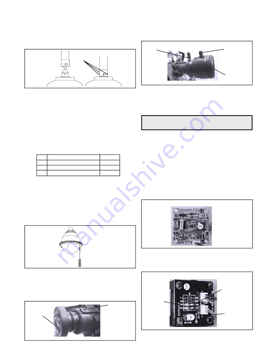
Vari-Focal Lens: First, adjust the Magnifi cation Lock Screw to
the desired magnifi cation (telephoto to wide
angle). Tighten the Lock Screw. Next, adjust
the Focus Lock Screw until a clear picture is
achieved. Tighten the Lock Screw (Figure 6).
Figure 6
Magnifi cation lock
screw
Focus lock
screw
Fixed iris
vari-focal lens
CAMERA SETTINGS
SERIAL NUMBERS BEGINNING WITH YK
FIXED AND FIXED VARI-FOCAL LENSES. There are no user
adjustable settings on these units (Figure 7).
Figure 7
AUTO IRIS LENSES. The dip switches are factory set with AES
off and backlight compensation on (Figure 8). The auto iris is also
set at the factory, but an adjustment screw is included for use if
needed. See page 10 for instructions on adjusting Auto Iris.
Auto Iris
adjustment
screw
AES Default Off
Backlight
Compensation
Default On
Figure 8
BW Fixed and Vari-Focal
BW Auto Iris
NOTE: To determine which camera is used in your unit, locate the
serial number on the inside of the housing. Match the two
letter prefi x with the corresponding instructions included
here for adjustments.


