Moog Videolarm IP ReadyTM Series Video Alarm FDW75C12N Product Instructions Download Page 14

-  -

INSTALLING QUICK RELEASE BRACKETS
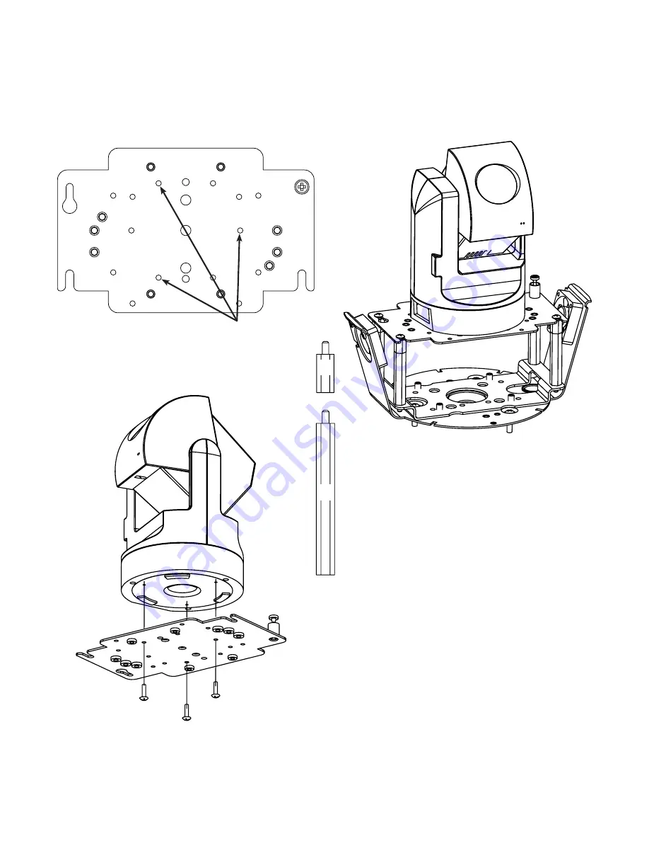
JVC VN-C30U

2539 Mounting Plate:

1.  Remove the mounting plate from the camera and 

place it onto the quick release bracket using the (3) 
metric 3M Phillips head screws provided with the kit.  
Then place the mounting plate back onto the 
JVC VN-C30U.

Attach camera using these (3) holes

½"

2"

2.  In the packet, there will be a number of 2 inch and 

½ inch spacers.  Take four of the ½ inch spacers and 
screw them onto the spacers that are on the base 
bracket (to make a 2½ inch spacer).  Place two 8/32 

s

 Philips head screws on the two and a half inch 

spacer in the dome.  Be sure to place the screws so 
they line up with the two open screw slots on the quick 
release bracket.  Place the JVC VN-C30U pan/tilt and 
quick release bracket in the housing, sliding the two 
open screw slots over the screws in the housing.  Slide 
the bracket forward, and then tighten the captive 
screw on the bracket. 

Summary of Contents for IP ReadyTM Series Video Alarm FDW75C12N

Page 1: ...Before attempting to connect or operate this product please read these instructions completely Product Instructions IP Ready Series FDW75C12N FDP75C12N 81 IN5329 04 28 06...

Page 2: ...charges The limited warranty stated in these product instructions is subject to all of the following terms and conditions 1 NOTIFICATION OF CLAIMS WARRANTY SERVICE If Purchaser believes that the Produ...

Page 3: ...IP Ready Network Housing with 12Vdc input wall mount or pendant mounting heater blowers ready for standard IP PTZ cameras ASSEMBLING THE UNIT Remove content from all boxes Contents should include Mai...

Page 4: ...cameras See specific instruction for the model that matches the unit you have INDEX OF CAMERAS AXIS 213 5 AXIS 214 6 CANON VB C10R 7 CANON VB C50iR 8 CANON VC C4R VC C50iR 9 ELMO PTC 200C 10 ELMO PTC...

Page 5: ...ng Use 4 2 spacer s plus 4 1 spacer s and 4 spacer s provided in the 2 hardware packets Attach camera using these 2 holes 1 2 Captive Screw 3 screws in housing 3 Place 3 8 x 32 x s Phillips head screw...

Page 6: ...2 The AXIS 214 camera requires 2 of spacing for optimal position within the housing Use the 4 2 spacers provided in the packet 3 Place 3 8 x 32 x s Phillips head screws on the top of the spacer as sho...

Page 7: ...ousing Use 4 2 spacer s plus 4 1 spacer s and 4 spacer s provided in the 2 hardware packets Attach camera using these 2 holes 1 2 3 Place 3 8 x 32 x s Phillips head screws on the top of the spacer as...

Page 8: ...housing Use 4 2 spacer s plus 4 1 spacer s and 4 spacer s provided in the 2 hardware packets Attach camera using these 2 holes 1 2 3 Place 3 8 x 32 x s Phillips head screws on the top of the spacer a...

Page 9: ...on within the housing Use 4 2 spacer s plus 8 1 spacer s provided in the 2 hardware packets Attach camera using these 2 holes 1 2 3 Place 3 8 x 32 x s Phillips head screws on the top of the spacer as...

Page 10: ...before proceeding 2539 Mounting Plate 1 Place the camera onto the quick release bracket using the 4 metric 3M Phillips head screws provided with the kit Attach camera using these 4 holes 1 2 2 The El...

Page 11: ...s provided with the kit Attach camera using these 4 holes 2 2 The Elmo PTC 201 camera requires 2 of spacing for optimal position within the housing Use 4 2 spacer s plus 4 spacer s provided in the 2 h...

Page 12: ...with the kit Attach camera using these 4 holes 1 2 2 The Elmo PTC 400C camera requires 3 5 of spacing for optimal position within the housing Use 4 2 spacer s plus 4 1 spacer s and 4 spacer s provided...

Page 13: ...1C Attach camera using these 4 holes 2 2 In the packet there will be a number of 2 inch and 1 inch spacers Take four of the 1 inch spacers and screw them onto the spacers that are on the base bracket...

Page 14: ...umber of 2 inch and inch spacers Take four of the inch spacers and screw them onto the spacers that are on the base bracket to make a 2 inch spacer Place two 8 32 X s Philips head screws on the two an...

Page 15: ...her provided 2 The Panasonic BB HCM381 KX HMC280 requires 3 of spacing to properly position the camera within the housing 3 Place 3 8 x 32 x s Phillips head screws on the top of the spacer as shown ab...

Page 16: ...of spacing to properly position the camera within the housing Use 4 spacers provided in the hardware packets 3 Place 3 8 x 32 x s Phillips head screws on the top of the spacer as shown above Be sure t...

Page 17: ...properly position the camera within the housing Use 4 2 spacers provided in the hardware packets 3 Place 3 8 x 32 x s Phillips head screws on the top of the spacer as shown above Be sure to place the...

Page 18: ...position the camera within the housing Use 4 2 spacers plus 4 spacers provided in the hardware packet 3 Place 3 8 x 32 x s Phillips head screws on the top of the spacer as shown above Be sure to plac...

Page 19: ...uires 3 of spacing to properly position the camera within the housing Use 4 2 spacers plus 4 1 spacers provided in the hardware packets 3 Place 3 8 x 32 x s Phillips head screws on the top of the spac...

Page 20: ...Alarm 2 Violet 3 Alarm 3 Gray 4 Common White Be sure the bracket is properly and securely mounted to a supporting structure capable of rigidly holding the weight of the entire unit INSTALLING THE HOUS...

Page 21: ...weight of the housing and drive unit The load will be subjected to vibration from the camera motor and wind 2 The wall mount bracket provided with the FDW7 includes a location for conduit entry If yo...

Page 22: ...22 Exploded View for Replacement Parts 1 11 6 9 10 1 1 1 2 3 5 4 7 8 14 16 6 12 13 18 1 1 3 2 2 2 8 4 2 1 1 4 4 1 3 4 3 3 1 1 4 4 1 1 4 4 19 17 1 1 2 Not included on 12Vdc housings...

Page 23: ...LS 24VAC ONLY 8 RPFD040 HOUSING HARDWARE 9 RPFD709 HOUSING TOP 10 RPFD2612 HOUSING TOP GASKET 11 WM10 WM10 WALL MOUNT 12 RPNET02 NETWORK HOUSINGS POWER BOARD NOT INCLUDED ON 12VDC UNITS 13 RPNET04 NET...

Page 24: ...24 2 000 3 250 R 733 2 132 2 981 1 537 5 500 Mounting Template...

Reviews: