background image

Page 1

Part No. XG0105B

ME34-DV-2 Homefire

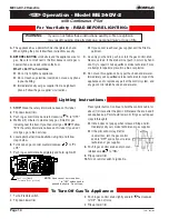
For Your Safety - READ BEFORE LIGHTING:

To Turn Off Gas To Appliance:

Lighting  Instructions:

  If you cannot reach your gas supplier, call the Fire 

Department.

C.

  Use only your hand to push in or turn the gas control knob. 

Never use tools. If  the knob will not push in or turn by 
hand, don't try to repair it, call a qualified service technician. 
Force or attempt to repair may result in a fire or explosion.

D.

  Do not use this appliance if any part has been under water. 

Immediately call a qualified service technician to inspect 
the appliance and to replace any part of the control system, 
and any gas control which has been under water.

A. 

This appliance is equipped with an ignition system that 
lights the pilot burner automatically. 

Do not attempt to 

light the pilot by hand.

B.  BEFORE LIGHTING

 smell all around the appliance area for 

gas.  Be sure to smell next to the floor because some gas 
is heavier than air and will settle on the floor.


What To Do If You Smell Gas:

  Do not try to light any appliance.

  Do not touch any electrical switch; do not use any 

phone in your building.

  Immediately call your gas supplier from a neighbour's 

phone. Follow the gas supplier's instructions.

1. 

Turn off remote switch.

2. 

Flip down lower trim.

3. 

Turn the switch on the gas control to "Off".

4. 

Flip up lower trim.

1.


STOP!  

Read the safety information above on this label.

2.

  Flip down lower trims.

3.

  Turn switch on the gas control to OFF".

4.

  Wait 5 minutes to clear out any gas.  If you smell gas,


STOP! 

Follow "B" in the safety information above on this 

label.  If you don't smell gas, go to the next step.

5.

  Turn switch on the gas control to "ON".

 NOTE:

 This unit is 

equipped with an ignition system that lights the pilot burner 
automatically. 

Do not attempt to light the pilot by hand.

6.

  Turn on wall switch.

7.

  Flip up lower trim.

8.

  If the fireplace does not operate, follow the instructions "To 

Turn Off Gas To Appliance" and call your service technician 
or gas supplier.

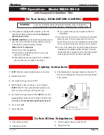
with Honeywell  Intermittent  Pilot

WARNING:


If you do not follow these instructions exactly, a fire or explosion 

may result causing property damage, personal injury or loss of life.

Operation -  Model ME34-DV-I-2 

ME34-DV-I-2

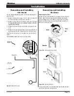
Gas

Inlet

Gas Control Switch
Shown in "On" Position

Summary of Contents for Homefire ME34-DV-2

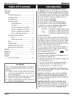
Page 1: ...ghbor s phone Follow the gas supplier s instructions If you cannot reach your gas supplier call the fire department Warning Improper installation adjustment altera tion service or maintenance can cause injury or property damage Refer to this manual For assistance or additional information consult a qualified installer service agency or the gas supplier For Your Safety Do not store or use gasoline ...

Page 2: ... 21 000 BTU H 7 6 Kilowatts Maximum Input 17 500 BTU H 5 1 Kilowatts Minimum Input Propane 21 000 BTU H 7 6 Kilowatts Maximum Input 17 500 BTU H 5 1 Kilowatts Minimum Input How to use this manual This manual covers installation operation and maintenance Light ing operation and care of this fireplace can be easily performed by the homeowner However all installation and service work should be perfor...

Page 3: ... sheetrock is not used behind the fireplace fram ing depth may be reduced to 15 Framing WARNING When this appliance is installed directly on carpeting tile or any combustible material other than wood flooring it must be installed on a metal or wood panel extending the full width and depth of the appliance Unprotected combustible walls which are perpendicular to the fireplace opening must not proje...

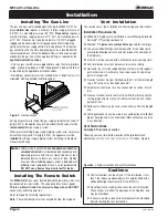
Page 4: ...and the main operating gas valve is located behind the removable brass trim at the bottom of the unit and need only be attached to the gas line with an approved fitting as required by the applicable installation codes Only use gas shut off valves approved for use by the state province region or governing body in which the appliance is being installed or as required by the applicable installation c...

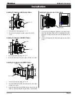
Page 5: ... 12 12 MOSR 1 Frame the termination opening to 12 x 12 2 Fasten the MOSR frame to the interior side of the studs using a minimum of 4 screws 3 Insert the termination into the MOSR frame as shown here and attach by screwing through the four pilot holes in the termination MSR MTO 3 MTO 3F MTO 3 MTKOG 1 Ensure that the two long mounting brackets are facing the bot tom of the termination See inset Thi...

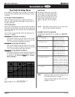
Page 6: ...floor of the fireplace is 78 and the horizontal run to the wall flange of the vent termination is 108 this would not be an accept able installation 0 12 24 36 48 60 72 84 96 108 132 120 144 156 168 180 Horizontal Run in Hearth 0 12 24 36 48 60 72 84 96 108 Figure 8 Heat Shield Install by sliding over the vent pipe where it passes through combustible construction Heat Shields Due to high flue tempe...

Page 7: ...place the height to the center of the termination is 44 Horizontal Venting Figure 9b Typical Top Vent installation The solid sections can be used in various combinations to obtain the desired vent run The vent run must fall within the limits set by the venting graph 90 Elbow MEXT Section Heat Shield Heat Shield MEL 90F F Elbow Termination Example 2 A 10 section and elbow MIHR 10 used in conjunctio...

Page 8: ...hen measured center to center of piping Example Typical vent installation 20 vertical vent 2 2 offsets required 25 of 20 5 max offset allowed This venting configuration meets requirements A Termination MVTK 1 B Flex sections MFL 1 12 section MFL 2 24 section MFL 3 36 section MFL 4 48 section C Solid sections MEXT 1 12 section MEXT 2 24 section MEXT 3 36 section MEXT 4 48 section D Support Ring Pla...

Page 9: ...ight Installation The height from the hearth to the center of the termination is 26 1 8 ME34 DV 2 Rear Vent versions are supplied with an 18 extension pipe EXT 18 with female female connections For shorter installations cut the EXT 18 to the desired length For extended installations use the EXT 18 section as supplied for an 18 vent run Note For Rear Vent models maximum horizontal run with no verti...

Page 10: ...ion from the hearth is 90 and the horizontal run to the wall flange of the vent termination is 126 this would be an acceptable installation Example C Unacceptable Installation If the vertical dimension from the floor of the fireplace is 78 and the horizontal run to the wall flange of the vent termination is 108 this would not be an accept able installation Figure 19 ME34 DV 2 Rear Vent Venting Gra...

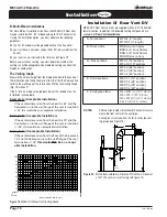
Page 11: ...45 Special care is recommended by the Master Painters and Decorators Association when painting the fireplace surrounds to select and ap ply a quality Alkyd sealer prior to the applying of latex paints This is to prevent leaching of water from evaporation and causing a brownish staining effect to paint over coats Top of fireplace Combustible Facing Combustible construction allowed in shaded area 1 ...

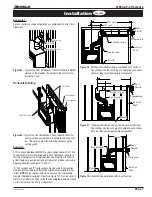
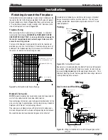
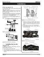
Page 12: ... to motor Figure 23b Wiring schematic for optional fan kit 115 1 60 Supply G L1 L2 Installing the Log Set Installing the Logs The ME34 DV 2 is supplied with six ceramic fibre logs Unpack the logs and handle them very carefully 1 Remove the door cover and the glass door 2 Place the Back log onto the back log rest as shown below in figure 8a The log has lip on the bottom which fits into the slot on ...

Page 13: ... bottom of the shell See Inset 2 Store the screws and clamps in a safe place to ensure that they are not lost To re install the insert simply reverse the steps above Figure 25 ME34 DV 2 insert INSET 1 Tab INSET 2 Mounting Bracket Fresh Air Flex 4 dia High temp silicone seal Venting Plate Front Slot Removing and Installing the Door Removing the Door Remove the trim as described on the next page to ...

Page 14: ...on Model ME34 DV 2 3 Push in gas control knob slightly and turn clockwise to Off Do not force 4 Flip up lower trim 1 Turn off remote switch 2 Flip down lower trim 1 STOP Read the safety information above on this label 2 Flip down lower trims 3 Push in gas control knob and turn clockwise to OFF 4 Wait five 5 minutes to clear out any gas Smell for gas including near the floor If you then smell gas S...

Page 15: ...o light any appliance Do not touch any electrical switch do not use any phone in your building Immediately call your gas supplier from a neighbour s phone Follow the gas supplier s instructions 1 Turn off remote switch 2 Flip down lower trim 3 Turn the switch on the gas control to Off 4 Flip up lower trim 1 STOP Read the safety information above on this label 2 Flip down lower trims 3 Turn switch ...

Page 16: ...rmal condition and is the result of burning of protective coatings on new metal Glass must be cleaned periodically to remove any film which is a normal biproduct of combustion which may be visible Film can easily be removed by removing the door as shown on page 13 Handle the door carefully and clean it with non abrasive glass cleaners One of the most effective products is Kel Kem Silicone seals on...

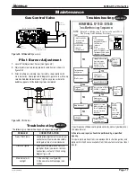
Page 17: ...e SV9500 SV9600 C heck T ransfo rm er LineVo lt Sup p ly Rep lace SV9500 SV9600 Saveo ld Ig niter Flam e Ro dA ssem b ly fo rservice INSET HSI Terminals C H EC K Linevo ltag ep o w er Lo wvo ltag e transfo rm er Lim itC o ntro ller Therm o stat W iring A irp ro vingsw itcho n co m b ustio nairb lo w ersystem Ventd am p er ifused iso p en andendsw itchm ad e Gas Control Valve Figure 28 Sit Nova 820...

Page 18: ...mponents not manufactured or supplied by The Companies 2 The Montigo Gas Appliance must be subjected to normal use The Gas Appliances are designed to burn gas only Burning conventional fireplace fuels such as wood coal or any other solid fuel will cause damage to the Gas Appliance will produce excessive temperatures and will result in a fire hazard Limitations On Liability It is expressly agreed a...

Page 19: ...the United States 6 feet 1 8 m minimum in Canada L clearance to nonmechanical air supply inlet to building or the combus tion air inlet to any other appliance 16 inches 41 cm minimum for appliances 100 000 BTU H 30kW M clearance to mechanical air supply inlet 6 feet 1 8 m minimum N clearance above paved sidewalk or a paved driveway located on public property 7 feet 2 1 m minimum P clearance under ...

Page 20: ...Canadian Heating Products Inc Langley BC V4W 4A1 Montigo Del Ray Corp Ferndale WA 98248 XG0105B Rev 07 07 02 ...

Reviews: