background image

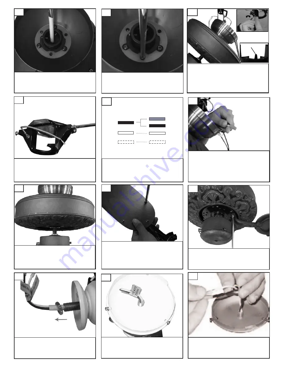
Place blade holders onto blades aligning holes in

blade holder with holes in blade.  Make sure that the

side of the blade you select is facing downward.

Install  3 screws and fiber washers to back side of

blade as shown.  Tighten screws securely. Repeat

this process 4 more times until all blades are assem-

bled.

Install blades to motor using the 10

motor screws provided.  Tighten

screws securely.

26

27

Lift fan to mounting bracket, aligning the “L”

shape holes on the canopy with the screws on

the mounting bracket.  Turn the fan  clock-

wise to lock in position.  Re-install the screws

removed in the previous step and tighten

securely.

25

Remove switch cap housing from fan.

Remove the plug from center of fit-

ter. Install switch cap housing to light

kit by turning clockwise to tighten.

29

Remove nut and save for next step.

28

Remove the all thread studs from the lower

part of the mounting bracket. 

Hang fan

from mounting bracket by the hands

free hook into a closed hole on the

edge of the Canopy.   Note: For

Canadian mounting refer to Step #8.

21

Hands free hook

Take 4 screws from hardware pack

and insert 2 one on each side of

bracket to match the L slot screw

holes in canopy.  Keep 2 screws for

later use. 

22

Replace the 3 screws removed and

tighten securely. Check motor for

shipping stabilizers and remove if

present.

20

Place canopy over fan body

aligning holes.

19

Make wire connections to power source using wire nuts
provided.  Make sure that no filiments are outside of
the wirenut. After making the wire connections, the
wires should be spread apart with the grounded con-
ductor and the equipment-grounding conductor on one
side of the outlet box and ungrounded conductor on
the other side of the outlet box.  

24

Connect black and blue wire from fan to Black or (Hot)

wire from house.  Connect White wire from Fan to

White (Neutral) wire from house.  Connect Ground

leads from mounting bracket and downrod to Ground

lead from house.  

Refer to Safety Tips section of

manual.

23

House

Fan

Blue 

Black

White

Green

Black

White

Ground

Install keeper nut over lead wires.

30

Summary of Contents for 5OR52XXD Series

Page 1: ...QUALITY CEILING FANS Ceiling Fan Installation Instructions For 5OR52XXD Series Fans READ AND SAVE THESE INSTRUCTIONS Total fan weight with light kit OWNER S MANUAL ...

Page 2: ...as those published by the National Fire Protection Association NFPA and the American Society for Heating Refrigeration and Air Conditioning Engineers ASHRAE and the local code authorities Before servicing or cleaning unit Switch power off at Service panel and lock service disconnecting means to prevent power from being switched on accidentally When the service disconnecting means cannot be locked ...

Page 3: ...di ia an n m mo ou un nt ti in ng g o on nl ly y Safety Cable Lag Screw 11 Make sure the studs protruding from the bottom of the Mounting bracket are installed with threads all the way through the bracket 9 Pass leadwires and safety cable through the canopy Remove side covers from canopy expos ing 4 holes 2 closed holes and 2 open L shape holes 16 F Fl lu us sh h M Mo ou un nt t I In ns st ta al l...

Page 4: ...he hands free hook into a closed hole on the edge of the Canopy Note For Canadian mounting refer to Step 8 21 Hands free hook Take 4 screws from hardware pack and insert 2 one on each side of bracket to match the L slot screw holes in canopy Keep 2 screws for later use 22 Replace the 3 screws removed and tighten securely Check motor for shipping stabilizers and remove if present 20 Place canopy ov...

Page 5: ...ack from light and white from fan to white from light by pushing connectors together 33 Install finial cap and finial nut to glass and tighten finial nut 37 Attach switch cap to fan by lining up 2 slot ear holes and 1 screw hole and twisting cap Then tighten the 3 screws 34 Install rubber washer and hex nut to glass tighten nut 36 Remove finial nut finial cap hex nut and washer from fitter 35 ...

Page 6: ...e unequal Check this level by selecting a point on the ceiling above the tip of one of the blades Measure this distance from blade tip to ceilng Keeping measure within 1 8 rotate the fan until the next blade is positioned for measurement Repeat for each blade If all blade levels are not equal you can adjust blade levels by the following procedure To adjust a blade tip down insert a washer not supp...

Reviews: