


13
attaching your Flatscreen TV
to the Tilting Vertical adjustment Bars
1
Locate the threaded inserts on your TV’s back
panel. Thread a screw from the set by hand into
one of the inserts to ensure it is the correct choice.
2
Thread screws through the adjustment bars
into the TV inserts with the rectangular washer,
if needed.
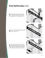
3
With a Phillips screwdriver, tighten the screws
so the adjustment bars are securely attached
to the TV.
The two vertical adjustment bars are designed
specifically for the left or right side of your TV. To
properly align them, place the vertical adjustment
bars with the screw holes and channels oriented
toward the outer edge of the back of your TV.
Your mounting system features 9 sets of screws of
varying diameter and length. Before attaching the
vertical adjustment bars to your display, determine
which screw set is correct for your display.
DO NOT lay your TV face down when
attaching the TV mounting plate. This
can cause permanent damage to your
screen. Lean it against a wall or other
solid surface so it remains vertically
upright.
DO NOT over tighten screws. Thread
screws carefully by hand before
tightening. If you feel any resistance,
remove the screw immediately.
The television should be unplugged
before threading any bolt or screw into
the back panel.