background image

Installation Instructions

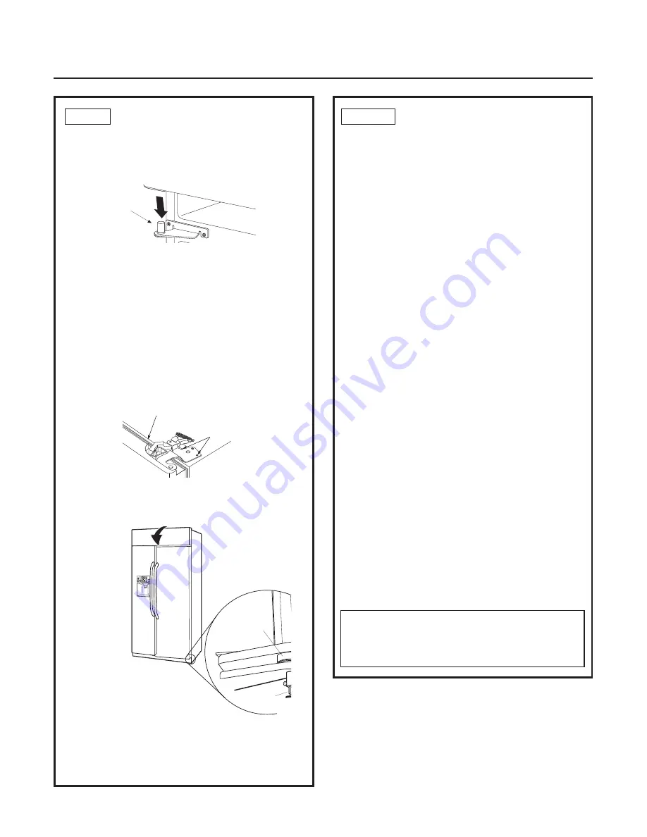
A.

Lower the refrigerator door onto the center hinge
pin. Ensure that the plastic hinge pin thimble is on
the center hinge pin or inside door hinge pin hole
located in the bottom of the door.

STEP 9  REPLACE FRESH FOOD DOORS

Hinge Pin

B.

Securely tape the door shut with masking tape 

or have a second person support the door.

C.

Insert the top hinge pin into the hinge hole on 
top of the refrigerator door. Make sure the door is
aligned with the cabinet and opposite door. Attach
the hinge to the top of the cabinet loosely with 
the bolts.

D.

Make sure the gasket on the door is flush against 
the cabinet and is not folded. Make sure the door 
is straight and the gap between the doors is even
across the front. While holding the aligned door 
in place, tighten the top hinge bolts.

Tighten Top
Hinge Bolts

Gasket Flush and Not Folded

E.

Follow the same procedure on the opposite door. 

F.

Reinstall the top cap using the 4 screws removed
earlier.

Bushing

Door Hi

nge

Case Hin

ge

7/32" Wrench

Ra

Clock

11

NOTE: 

Commonwealth of Massachusetts Plumb ing

Codes 248CMR shall be adhered to. Saddle valves 
are illegal and use is not permitted in Massachusetts.
Consult with your licensed plumber.

STEP 10   INSTALL WATER LINE

• A cold water supply is required for automatic icemaker

operation. The water pressure must be be tween 40 and
120 p.s.i.

• Route GE SmartConnect

Refrigerator Tubing or 1/4" OD

copper tubing between house cold water line and the
water connection location.

• Measure the distance from the water valve on the back

of the refrigerator to the water supply line. Add 8 foot
length to allow the refrigerator to be moved away from
the wall after installation. Bend the tubing into 3 coils 
of about 10".

NOTE: The only GE approved plastic tubing is supplied 
in GE SmartConnect

Refrigerator Tubing kits. Do not

use any other plastic water supply line because the line
is under pressure at all times. Certain types of plastic
will crack or rupture with age and cause water damage
to your home.

GE SmartConnect

Refrigerator Tubing Kits are 

available in the following lengths:

2' (0.6 m)

– WX08X10002

6' (1.8 m)

– WX08X10006

15' (4.6 m)

– WX08X10015

25' (7.6 m)

– WX08X10025

Shut off the main water supply.

Turn on the nearest faucet long enough to clear the line 
of water.
• Install a shut-off valve between the icemaker water 

valve and cold water pipe in a basement or cabinet. 
The shut-off valve should be located where it will be 
easily accessible.

• Turn on the main water supply and flush debris. 

Run about a quart of water through the tubing into 
a bucket. Shut off water supply at the shut-off valve.

NOTE: 

Saddle type shut-off valves are included 

in many water supply kits, but are not recommended
for this application.

Summary of Contents for WX08X10002

Page 1: ...Installation Instructions Stainless Steel Free Standing Drawer Freezer Refrigerator monogram com 31 46547 225D1974P007...

Page 2: ...e to leave these instructions with the Consumer Note to Consumer Keep these instructions with your Owner s Manual for future reference WARNING This appliance must be properly grounded See Grounding th...

Page 3: ...al Locations The opening must be prepared with the electrical and water supply located as shown Additional Specifications A 115 volt 60Hz 15 or 20 amp power supply is required An individual properly g...

Page 4: ...on and place under the refrigerator where you are working GROUNDING THE REFRIGERATOR IMPORTANT Please read carefully FOR PERSONAL SAFETY THIS APPLIANCE MUST BE PROPERLY GROUNDED The power cord of this...

Page 5: ...s with a pencil nail or awl Floor Concrete 2 Holes Floor Wood 2 Holes Base Bracket on the Refrigerator RH Holes 7 1 4 Rear RH Corner of Cabinet Wall RH Side of Refrigerator Locator Template Sheet 2 Wa...

Page 6: ...e 2 or preferably 4 10 16 hex head screws tightly into place as illustrated in Figure 3 Figure 3 Attachment to Wall and Floor STEP 2B INSTALL ANTI TIP BRACKET CONT CONCRETE Wall and Floor Construction...

Page 7: ...OVE THE FREEZER DRAWERS The freezer drawers can be removed if needed to fit through tight areas Read these instructions completely and carefully REMOVE THE BASKET A Open the freezer drawer until it st...

Page 8: ...om each side of the rail assembly B Remove the four screws attaching the slide brackets to the connector brackets C Remove the connector brackets and place aside D Tilt the bottom drawer toward the re...

Page 9: ...only Move the refrigerator indoors Place refrigerator close to the installation location 9 REPLACE THE FREEZER BASKET Replace the top drawer freezer basket B Drive the bottom outside screw into the do...

Page 10: ...assembly and drive screws into slide bracket two screws on each side 10 STEP 8 REPLACE THE FREEZER DRAWERS CONT REPLACE THE 2 PIECE BASKET Place the rear of the basket onto the metal slide brackets Th...

Page 11: ...quired for automatic icemaker operation The water pressure must be between 40 and 120 p s i Route GE SmartConnect Refrigerator Tubing or 1 4 OD copper tubing between house cold water line and the wate...

Page 12: ...ert the end of the copper tubing into the refrigerator connection at the back of the refrigerator as far as possible Hold the tubing in place and tighten the fitting If you are using GE SmartConnect t...

Page 13: ...ve as a stabilizing brake to hold the refrigerator securely in position during operation and cleaning The leveling legs also prevent the refrigerator from tipping Turn the leveling legs clockwise to r...

Page 14: ...It will take 2 3 days to fill the ice bin NOTE In lower water pressure conditions the water valve may turn on up to 3 times to deliver enough water to the icemaker STEP 18 TEMPERATURE CONTROLS The tem...

Page 15: ...15 Notes...

Page 16: ...in your area call 1 800 444 1845 NOTE Product improvement is a continuing endeavor at General Electric Therefore materials appearance and specifications are subject to change without notice 31 46547...

Reviews: