background image

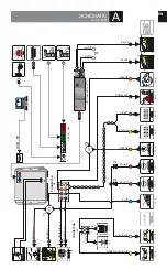
SCHEMATIC

A

V. 001/2016

DS 410

DS 410

BROWN

BROWN

BLUE

YELLOW

VIOLET

PINK/BLACK

ORANGE

ORANGE

BROWN

RED/BLUE

BLACK

RED

*1

*2

*2

*3

*4

CONNECTOR

J1

CONNECTOR

J2

J1 - 1

12V/24V12V/24V

BROWN

LIGHT BLUE

GREEN/LIGHT BLUE

GNDGND

BLACK

J1 - 2

J2 - 7

J2 - 8

J2 - 4

J2 - 7

CAN L

CAN L

CAN H

CAN H

 O

N


C

C

A                 K

C

O L

 O

N


C

C

A                 K

C

O L

DIGIT

AL

DIGIT

AL

ST

A

TUS 3

J2 - 7

J2 - 7

J2 - 6

J2 - 1

J2 - 2

J2 - 6

J1 - 3

J1 - 4

J2 - 3

OR

OR

ST

A

TUS 1
ST

A

TUS 1

ST

A

TUS 2
ST

A

TUS 2

Rx

Tx

LEDLED

ADDITIONAL


SENSOR

ADDITIONAL


SENSOR

USB - PC

J2 - 5

PERIMETERPERIMETER

BLACK

WHITE

WHITE

BLACK

PAGERPAGER

IMMOBILISERIMMOBILISER

IMMOBILISERIMMOBILISER

OPTIONAL

 MODULE

RED

GREEN

EN

4

max 10Amax 10A

max 10Amax 10A

SIRENSIREN

Summary of Contents for MAP77

Page 1: ...MAP77 CanBus Vehicle Security System INSTALLATION...

Page 2: ...must be disconnected If for some reasons disconnecting battery is impossible during the installation the cable loom must be disconnected from VSS central unit All the connections must be isolated the...

Page 3: ...must be disconnected If for some reasons disconnecting battery is impossible during the installation the cable loom must be disconnected from VSS central unit All the connections must be isolated the...

Page 4: ...d signal black wire can be switched on when armed can be used as windows roll up analogue output or as a constant ground for RF module Always check the installation diagram for particular vehicle CAN...

Page 5: ...st time USB device drivers will be automatically installed System will ask where the drivers are located on disc Software is easy and intuitive to operate The software can select vehicle make and mode...

Page 6: ...EN...

Page 7: ...VSS 9x ignition switch 10x oem alarm 11x trigger from positive input orange wire Opel Meriva In order to go to stage II press and hold PA button aprox 3 seconds until siren chirps 2x Stage II testing...

Page 8: ...are drawn on car part of schematic brown wire of MAP77 cannot be used as PAGER output or 2nd IMMOBILISER output 2 Use diodes only if both STATUS 1 and STATUS 2 wires are drawn on car part of schematic...

Page 9: ...2 J2 7 J2 8 J2 4 J2 7 CAN L CAN L CAN H CAN H O N CCA KCOL O N CCA KCOL DIGITAL DIGITAL STATUS 3 J2 7 J2 7 J2 6 J2 1 J2 2 J2 6 J1 3 J1 4 J2 3 OR OR STATUS 1 STATUS 1 STATUS 2 STATUS 2 Rx Tx LED LED A...

Reviews: