background image

54D5031 

7

B

A

D

F

H

A

E

C

1/2” or 5/8”

C

A

A

C

G

G

1/2” or 5/8”

1/2” or 5/8”

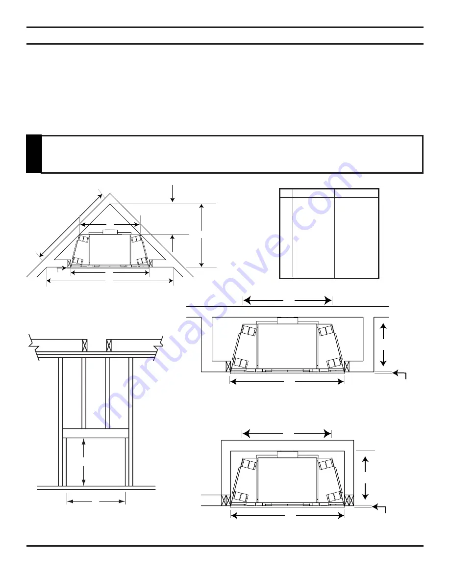
FIREPLACE FRAMING 

Firebox framing can be built before or after the appliance is set in place. Construct firebox framing following Figure 2 and 
the chart below for your specific installation requirements. See Figure 3 on Page 8 for firebox dimensions.  The framing 
headers may rest on the top of the firebox standoffs. Do not bring headers below top of standoffs.
The firebox may be installed directly on a combustible floor or raised on a platform of an appropriate height. When the 
firebox is installed directly on carpeting, tile, or other combustible material, other than wood flooring, the firebox shall be 
installed on a metal or wood panel extending the full width and depth of the enclosure.

Corner Installation 

 Stud Location 

Inside Chase Installation 

Figure 2 - Framing Dimensions 


300 400 

 A 

33

1

/

2

" 37

1

/

2

"

 B 

37

1

/

4

" 40

7

/

8

"

 C 

28

1

/

4

" 29

1

/

4

"

 D 

14

1

/

8

" 13

1

/

2

"

 E 

55

11

/

16

" 60

7

/

8

"

 F 

27

13

/

16

" 30

7

/

16

"

 G 

13

3

/

4

" 16

1

/

2

"

 H 

 39

3

/

8

" 43

1

/

16

"

PRE-INSTALLATION INFORMATION  

Do not 

fi

 ll spaces around 

fi

 rebox with insulation or other materials. This could cause 

fi

 re. 

W

ARNING

Summary of Contents for Direct Vent Gas Fireplace HBDV300

Page 1: ...taller service agency or the gas supplier This appliance may be installed in an aftermarket permanently located manufactured home USA only or mobile home where not prohibited by local codes This appliance is only for use with the type of gas indicated on the rating plate This appliance is not convertible for use with other gases unless a certified kit is used Aftermarket Completion of sale not for...

Page 2: ...on 28 Check Gas Type 28 Installing Gas Piping to Fireplace Burner System Location 28 Checking Gas Pressure 30 Electrical Installation 30 Electrical Wiring 30 Remote Wall Mounted Switch 31 Remote Wall Switch 31 Optional DC Remote Systems 31 Optional Fan 31 Glass Removal Brick Installation 32 Final Installation 33 35 Placement of lava rock rock wool and logs 33 35 Installing Andirons 35 Operating In...

Page 3: ...f this unit is not properly installed by a qualified service person with glass door properly seated and sealed combustion leakage can occur CARBON MONOXIDE POISONING Early signs of carbon monoxide poisoning are similar to the flu with head aches dizziness and or nausea If you have these signs the fireplace may not have been installed properly Get fresh air at once Have the fireplace inspected and ...

Page 4: ...all a qualified service person to arrange for replacement of the unit 19 Do not operate fireplace if any log is broken 20 Do not use a blower insert heat exchanger insert or any other accessory not approved for use with this fireplace 21 Do not operate the fireplace with glass door removed cracked or broken IMPORTANT PLEASE READ THE FOLLOWING CAREFULLY It is normal for fireplaces fabricated of ste...

Page 5: ...i ance is a product thermal efficiency rating determined under continuous operating conditions and was deter mined independently of any installed system Thermal efficiency up to 75 AFUE efficiency up to 71 CODE APPROVAL Direct Vent type appliances draw all combustion air from outside of the dwelling through the vent pipe These appliances have been tested by CSA and found to comply with the establi...

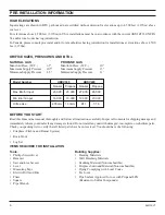
Page 6: ...Materials Hammer Wall Finishing Materials Saw and or saber saw Caulking Material Noncombustible Level Fireplace Surround Material Noncombustible Measuring Tape Piping Complying with Local Codes Electric Drill and Bits Tee Joint Pliers Pipe Sealant Approved for use with Propane LPG Square Resistant to Sulfur Compounds Pipe Wrench Model Number HBDV300 HBDV400 Natural Propane Natural Propane Max Btu ...

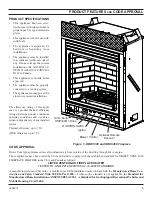
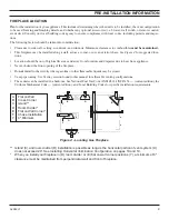
Page 7: ...talled directly on a combustible floor or raised on a platform of an appropriate height When the firebox is installed directly on carpeting tile or other combustible material other than wood flooring the firebox shall be installed on a metal or wood panel extending the full width and depth of the enclosure Corner Installation Stud Location Inside Chase Installation Figure 2 Framing Dimensions 300 ...

Page 8: ...R Pipe Rear L R D 161 2 181 2 Rear Width E 28 29 Glass Height F 18 203 8 Total Height G 337 8 405 8 Depth H 15 181 4 Figure 3 Fireplace Dimensions DESCRIPTION Key Letter HBDV300 HBDV400 Height to Standoffs I 37 405 8 CTR Pipe Height Rear J 295 8 331 8 Top Face K 21 8 11 4 Side Face L 11 2 21 2 Bottom Face M 15 16 15 16 Non combustible N 51 4 61 8 Chassis Height O 333 4 371 2 FIREPLACE DIMENSIONS ...

Page 9: ...re and draperies due to heat from appliance Never obstruct the front opening of the fireplace Do not install in the vicinity where gasoline or other flammable liquids may be stored Vent pipe routing See Venting section found in this manual for allowable venting configurations These units can be installed in a bedroom See National Fuel Gas Code ANSI Z233 1 NFPA 54 current edition the Uniform Mechan...

Page 10: ...l flooring the appliance shall be installed on a metal wood or noncombustible material panel extending full width and depth of the appliance WARNING CLEARANCES CLEARANCES TO COMBUSTIBLES MANTEL CLEARANCES NOTE The combustible area above the facing must not protrude more than 3 4 from the facing If it does it is considered a mantel and must meet the mantel requirements listed in this manual Figure ...

Page 11: ...place to the floor Use four 4 screws to attach fireplace to framing The side nailing flanges are 1 2 or 5 8 to accommodate different wall thickness SECURING FIREPLACE TO FLOOR OR FRAMING Figure 6 Securing Fireplace to Floor and Framing Studs Insulation Board Framing Nail Flange Screws Nail Flange Screws Screws Screws Screws WARNING DO NOT REMOVE INSULATION BOARD ...

Page 12: ... rooftops Be aware of electrical wiring locations in walls and ceilings The following actions will void the warranty on your venting system Installation of any damaged venting component Unauthorized modification of the venting system Installation of any component part not manufactured or approved by MHS Installation other than permitted by these instructions FINISHING MATERIAL NOTE Any remote wiri...

Page 13: ...of this vent system require a minimum of 3 clearances to combustibles at the top of the flue and 1 clearance at the sides and bottom until the flue penetrates the outside wall A minimum 1 clearance all around the flue is acceptable at this point of penetration Vertical sections of this vent system require a minimum of 1 clearance to combustibles on all sides of the pipe A Minimum of 3 Clearance to...

Page 14: ...fitted as required 1 Remove the eight 8 screws securing the flue pipe adapter to the fireplace body See Figure 9 2 Set the flue pipe adapter aside complete with the gasket Do not damage the gaskets as the adapter and gasket must be refitted 3 Remove the eight 8 screws securing the flue pipe cover to the top of the intake box and remove the cover and gasket See Figure 9 4 Remove the six 6 screws se...

Page 15: ... each floor level If an offset is needed in the attic additional pipe and elbows will be required You may use a chase with a vent termination with exposed pipe on the exterior of the house See Installing Vent System in a Chase below If pipe is enclosed in chase it is not exposed It is very important that the venting system maintain its balance between the combustion air intake and the flue gas exh...

Page 16: ...event condensation on window D Vertical clearance to ventilated soffit located above the terminal within a horizontal distance of two 2 feet 610mm from the centerline of the terminal 18 457mm minimum E Clearance to unventilated soffits 12 305mm minimum Clearance to vinyl soffit 30 762mm F Clearance to an outside corner See Figure 12 G Clearance to an inside corner See Figure 12 H Not to be install...

Page 17: ...the vertical and horizontal dimensions of the vent system 1 Determine the height of the center of the horizontal vent pipe exiting through the outer wall Using this dimension on the Sidewall Vent Graph below locate the point intersecting with the slanted graph line 2 From the point of this intersection draw a vertical line to the bottom of the graph 3 Select the indicated dimension and position th...

Page 18: ...lar s tabs Attach Simpson s DirectVent Pro by fully inserting into the collar and securing with self tapping screws The screws shall only penetrate the flue outer wall Refer to vent manufacturer s installation instructions to properly assemble flue 2 Locate and cut the vent opening in the wall For combustible walls first frame in opening Combustible Interior Walls Cut a 111 2 H x 91 2 W hole throu...

Page 19: ...to All Four Sides Vent Cap Wood Screw Cut Vinyl Siding Away to Fit Standoff Wood Screw Simpson Termination 985 Bolt Apply Mastic to All Four Sides Nut Standof 950 Figure 20 Installing Firestop on Horizontal Vent Pipe Interior Wall Surface Firestop Horizontal Vent Pipe Screw Vent Cap Horizontal Termination A vinyl siding standoff part 950 must be used with the Simpson Selkirk Horizontal Termination...

Page 20: ...t exits through foundations less than 20 below outcrop the termination must be flush up with outcropped wall above It is best to locate the fireplace in such a way that minimizes the number of offsets and horizontal vent length The horizontal vent run refers to the total length of vent pipe from the flue collar of the fireplace or the top of the Transition Elbow to the face of the outer wall Figur...

Page 21: ...on A plus B must not be greater than 17 5 2m The maximum number of 45 elbows permitted per side wall installation is two 2 These elbows can be installed in either the vertical or horizontal run For each 45 elbow installed in the horizontal run the length of the horizontal run MUST be reduced by 18 45cm This does not apply if the 45 elbows are installed on the vertical part of the vent system The m...

Page 22: ...base of snorkel Install drain pipe Install window well not supplied Refill hole with 12 of coarse gravel leaving a clearance of approximately 4 below snorkel See Figure 26 3 Install vent system 4 Ensure a watertight seal is made around the vent pipe coming through the wall 5 Apply high temperature sealant caulking supplied around the 4 and 7 snorkel collars 6 Slide the snorkel into the vent pipes ...

Page 23: ...by 18 450mm Example Maximum horizontal length No elbows 10 3m 1x45 elbows 8 5 2 6m 2x45 elbows 7 2 1m A minimum of an 8 2 5m vertical rise is required Two sets of 45 elbows offsets may be used within the vertical sections From 0 to a maximum of 8 2 5 m of vent pipe can be used between elbows See Figure 29 The maximum angular variation allowed in the system is 270 See Figure 29 1 2 3 4 1 2 3 4 Exam...

Page 24: ...ine plumb down from the ceiling to the position of the flue exit Mark the center point where the vent will penetrate the ceiling Drill a small locating hole a this point Drop a plumb line from the inside of the roof to the ceiling locat ing hole in the ceiling Mark the center point where the vent will penetrate the roof Drill a small locating hole at this point FLAT CEILING INSTALLATION 1 Cut a 91...

Page 25: ...eep roof pitches Nearby trees adjoining roof lines steep pitched roofs and other similar factors may cause poor draft or down drafting in high winds Increasing the vent height may solve this problem NOTE If the vent pipe passes through any occupied areas above the first floor including storage spaces and closets you must enclose pipe You may frame and sheetrock the enclosure with standard construc...

Page 26: ... flexible venting Over tightening clamps may rip tear or otherwise damage flexible venting The adaptor kit does not include individual pipe sections which may be purchased separately UL1777 listed type flex venting only 3 Start the flexible vent as follows A Installing the inner flex adaptor and pipe see Figure 1 1 Insert the long side of the 4 inner ring inte exhaust pipe gently tap to seat into ...

Page 27: ...cribed by the flexible vent manufacture and in such a way as to maintain concentric inner and outer vent spacing D Attaching flexible venting to vertical termination assemblies 1 When using Simpson pipe a MHS flex to pipe adaptor and or rigid pipe section s is required to connect the flexible vent assembly to the vertical termination by using three self penetrating screws 2 Review Figure 4 and cor...

Page 28: ...ALLING GAS PIPING TO FIREPLACE BURNER SYSTEM LOCATION INSTALLATION ITEMS NEEDED Before installing fireplace and burner system make sure you have the items listed below External regulator supplied by installer Piping check local codes Sealant resistant to propane LP gas Equipment shutoff valve Test gauge connection Sediment trap recommended Tee joint Pipe wrench approved flexible gas line with gas ...

Page 29: ...rip leg in supply line as shown in Figure 40 Locate sediment trap drip leg where it is within reach for cleaning Install in piping system between fuel supply and burner system Locate sediment trap drip leg where trapped matter is not likely to freeze A sediment trap collects moisture and contaminants and keeps them from going into the burner system gas controls If sediment trap drip leg is not ins...

Page 30: ...sure reading be sure and turn captured screw clockwise firmly to reseal Do not over torque Check test points for gas leaks Figure 41 Gas Pressure Check at Gas Valve Pressure Test IN Pressure Test OUT HI LO Knob Pilot Adjustment Screw Verify proper operation after servicing ELECTRICAL WIRING This fireplace will work without any electrical supply except to operate blower and electronic ignition syst...

Page 31: ...for the fan blower systems has been factory installed This system requires that 110 120 VAC to be wired to the factory installed junction box before the fireplace is permanently installed See Figure 43 TAN TAN WHITE GREEN BLACK BLACK BLACK SPEED CONTROL OPTIONAL THERMOSTATIC SWITCH REMOTE WALL MOUNTED SWITCH A remote wall switch and up to fifteen 15 feet of 18 gauge wire may be used with this appl...

Page 32: ...nter firebrick panel on the back wall first Stand firebrick panel straight up against the back of fireplace with the bottom edge at bottom of inner firebox 4 Repeat Step 3 with the left and right side firebrick panels Secure the top of each side firebrick panel to the fireplace with one retainer bracket and one screw 5 Use a screw gun to drive in the self drilling screw into the sheet metal throug...

Page 33: ... the unit to establish yellow flame in the front See Figure 46 4 Place log 1 into place by setting the log over the two pins on the grate toward the back The two round holes on the bottom of the logs should go over the two pins on the grate See Figure 47 5 Place log 2 into place by matching the two holes on the bottom of the log with the two pins located on top of the burner When this log is in pl...

Page 34: ...the two notches on the bottom of this log with the two protrusions on log 1 2 This log when seated fits in the middle above logs 1 2 See Figure 50 8 Place log 5 into place by matching the two notches on the bottom of this log with the two protrusions on log 1 2 This log when seated is positioned toward the right See Figure 51 9a For 400 models place log 6 into place toward the left by sitting the ...

Page 35: ...iron hole Lower andiron hole Top bracket slot Lower bracket slot Horizontal fireplace grate bar Figure 55 Universal Andirons Figure 54 a b Andiron Placement 400DVBH and 300DVBH INSTALLING UNIVERSAL ANDIRONS Bolt bracket through lower slot into top andiron hole Slide clip over horizontal fireplace grate bar See Figure 55 ...

Page 36: ...pair may result in a fire or explosion D Do not use this appliance if any part of it has been under water Immediately call a qualified service tech nician to inspect the appliance and to replace any part of the control system and any gas control that has been under water If you do not follow these instruction exactly a fire or explosion may result causing property damage personal injury or loss of...

Page 37: ...he lighting operation The gas control knob is designed to be operated by hand DO NOT use any tools during this operation Damaged knobs may result in serious injury WARNING 1 Depress and turn knob counterclockwise to pilot position 2 Depress fully and hold pilot gas knob Depress piezo igniter as many times as needed to ignite pilot Keep knob fully depressed for a few seconds Release and check that ...

Page 38: ...n off the main burner without using the gas valve knob Make sure the button is in the ON position to light the main burner See Figure 57 LIGHTING THE BURNER Depress and turn the knob counterclockwise to the ON position See Figure 58 It will take less than four 4 seconds for the burner to ignite PILOT POSITION Depress and turn knob to pilot position to keep burner off while maintaining the pilot li...

Page 39: ... in operation See Figure 61 The pilot flame has three distinct flames one engulfing the thermopile one engulfing the thermocouple and the other reaching to the main burner BURNER Inspect area around the injector Remove any lint or foreign material with a brush or vacuum BURNER FLAME The flames from the burner should be visually checked as soon as the heater is installed and periodically during nor...

Page 40: ...d Handle glass door with care to avoid striking or scratching it on hard objects To clean glass door follow Glass Removal procedure outlined in the Final Installation section Film deposit on the inside of the glass should be cleaned off using a nontoxic non corrosive non abrasive mild cleaning solution Simply apply an adequate amount to the glass and wipe off with a damp cloth After all maintenanc...

Page 41: ...nnection at the gas valve is fully inserted and tight Disconnect the thermocouple from the valve place one millivolt lead wire on the tip of the thermocouple and the other meter lead wire on the thermocouple copper lead Start the pilot and hold the valve knob in If the millivolt reading is less than 15 mV replace pilot assembly B If thermocouple is producing more than 15 mV replace faulty valve A ...

Page 42: ...e for maximum flame impinge ment on thermocouple A Check for flue product leak Replace defective pipe section B Check horizontal venting piping is running upward 1 4 per foot Do not run the pipe level or downward C Check for proper installation and freedom from debris or block age A Install log set per the instructions Inspect the injector and air intake area Make sure this area does not have any ...

Page 43: ...54D5031 43 1 2 3 5 6 7 10 4 9 11 REPLACEMENT PARTS FIREPLACE COMPONENTS ...

Page 44: ... Firebrick Center CC 1 26D7069 26D7077 6 Standard Firebrick Right CC 1 26D7068 26D7076 7 Standard Firebrick Left CC 1 26D7068 26D7075 5 Standard Firebrick Center CR 1 26D7097 26D7105 6 Standard Firebrick Right CR 1 26D7096 26D7104 7 Standard Firebrick Left CR 1 26D7096 26D7103 8 Cottage Clay Firebrick Walls 1 FB300CCW FB400CCW 8 Cottage Red Firebrick Walls 1 FB300CRW FB400CRW 9 Brass Curved Design...

Page 45: ...54D5031 45 8A HBDV400 8B HBDV300 11 12 13 14 15 3 4 5 6 7 8 2 1 2T 2I 2C 10 REPLACEMENT PARTS MILLIVOLT ENGINE ...

Page 46: ...503 14D0503 7 Injector 1 62D3006 20H3156 62D3004 33D5039 8 Burner Assembly 1 54D5115 54D5115 54D5006 54D5006 9 Venturi 1 45D0600 45D0600 45D0600 45D0600 10 Wire Assembly 1 44D0500 44D0500 44D0500 44D0500 10 Wire Assembly 1 44D0501 44D0501 44D0501 44D0501 ACCESSORIES 11 Thermostatic RCT RCST RCT RCST RCT RCST RCT RCST Remote Control 1 WWTD RCSTE WWTD RCSTE WWTD RCSTE WWTD RCSTE 12 Remote Control RC...

Page 47: ...w Profile Vertical Termination Cap 46DVA VC 980 4DT VC 1 1 Square Horizontal Termination Cap aluminum 46DVA HC 985 4DT HC Round Horizontal Termination Cap Square Base aluminum 46DVA HRCS Sconce Termination Cap aluminum 46DVA HSC 8 6 Storm Collar 46DVA SC 953 4DT SC 9 6 1 Firestop 46DVA FS 963 4DT FS 10 1 Vinyl Siding Standoff 46DVA VSS 950 4DT VS Attic Insulation Shield 46DVA IS 3 6 6 Pipe Length ...

Page 48: ...0 HBDV400 1 Rear Log 1 54D5119 54D5023 2 Right Log 1 54D5120 54D5024 3 Left Log 1 54D5121 54D5025 4 Mid Top Log 1 54D5123 54D5026 5 Right Top Log 1 54D5122 54D5027 6 Left Front Log 1 54D5124 54D5028 7 Right Front Twig 1 N A 54D5029 LOGS REPLACEMENT PARTS ...

Page 49: ...n 7 feet above finished grade in the area of the venting including but not limited to decks and porches the following requirements shall be satisfied 1 INSTALLATION OF CARBON MONOXIDE DETECTORS At the time of installation of the side wall horizontal vented gas fueled equipment the installing plumber or gasfitter shall observe that a hard wired carbon monoxide detector with an alarm and battery bac...

Page 50: ...tial purposes c MANUFACTURER REQUIREMENTS GAS EQUIPMENTVENTING SYSTEM PROVIDED When the manufacturer of Product Approved side wall horizontally vented gas equipment provides a venting system design or venting system components with the equipment the instructions provided by the manufacturer for installation of the equipment and the venting system shall include 1 Detailed instructions for the insta...

Page 51: ...54D5031 51 NOTES ...

Page 52: ...52 54D5031 NOTES ...

Page 53: ...54D5031 53 NOTES ...

Page 54: ...the installation instructions The Limited Lifetime Warranty will also be void if the appliance is not operated and maintained according to the operating instructions supplied with the appliance and does not extend to 1 firebox burner assembly damage by accident neglect misuse abuse alterations negligence of others including the installation thereof by unquali fied installers 2 the costs of removal...

Reviews: