background image

10

Deutsch

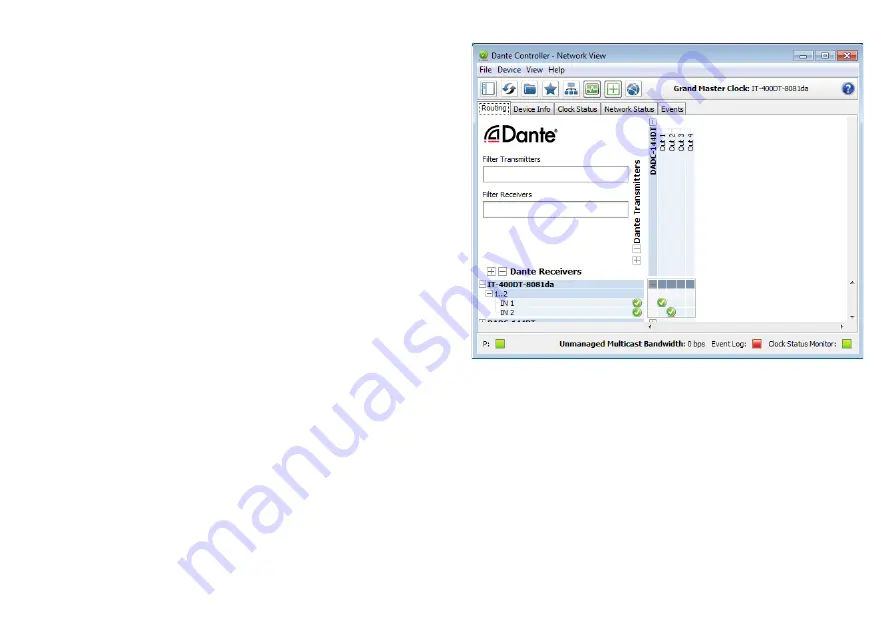
4.3 Routing mit dem Dante-Controller

Für die Zuweisung der Eingangs- und Ausgangssignale der beteiligten 
Geräte:
1)  Im „Network View“-Fenster unter „Routing“ die Sendekanäle des 

gewünschten Dante-Transmitters unter „Dante Transmitters“ sowie 
die Empfangskanäle des IT-400DT unter „Dante Receivers“ durch 
Klicken auf das 

 öffnen (

 Abb . 3) .

2)  Ausgehend von der Spalte des Dante- Transmit-Kanals bis zur Zeile 

des gewünschten Dante-Receive-Kanals vom IT-400DT navigieren 
und auf das Feld am Schnittpunkt klicken .

3)  Warten bis das Feld einen grünen Kreis mit weißem Haken 

 an-

zeigt .

4)  Die letzten zwei Schritte optional für den zweiten Dante-Re ceive-

Kanal des IT-400DT vornehmen .

Abb. 3   Audio-Routing von der Tonquelle „DADC-144DT“ 

zum Empfänger „IT-400DT“

Auf der Audinate-Website kann zum Dante-Controller ein englisches 
Benutzerhandbuch (User Guide) heruntergeladen werden unter: 


https://www .audinate .com/resources/technical-documentation

Summary of Contents for IT-400DT

Page 1: ...ONICS FOR SPECIALISTS ELECTRONICS FOR SPECIALISTS ELECTRONICS FOR SPECIALISTS ELECTRONICS FOR SPECIALISTS BEDIENUNGSANLEITUNG INSTRUCTION MANUAL Aktives Musikhorn für Dante Netzwerke Active Music Horn for Dante Networks IT 400DT Bestellnummer Order Number 16 3870 ...

Page 2: ...2 ...

Page 3: ...3 ELECTRONICS FOR SPECIALISTS ELECTRONICS FOR SPECIALISTS ELECTRONICS FOR SPECIALISTS ELECTRONICS FOR SPECIALISTS ELECTRONICS FOR SPECIALISTS ELECTRONICS Deutsch Seite 4 English Page 32 ...

Page 4: ...nsters 16 6 2 6 Programm beenden 17 6 3 Signalverarbeitung konfigurieren 18 6 3 1 Signalweg 18 6 3 2 Ansicht MAIN 20 6 3 3 Ansicht IN A B 22 6 3 4 Gruppensteuerung 24 6 4 Zugriffsrechte verwalten 26 6 4 1 Passwörter eingeben 26 6 4 2 Passwörter ändern 26 6 4 3 Zugriffsrechte ändern 26 6 5 Locked State 26 6 6 Standby 26 6 6 1 Automatischer Standby 26 6 7 Einschalteinstellungen festlegen 26 6 8 Sich...

Page 5: ...ttel oder Chemikalien Wird das Gerät zweckentfremdet nicht richtig angeschlossen falsch bedient oder nicht fachgerecht repariert kann keine Haftung für da raus resultierende Sach oder Personenschäden und keine Garantie für das Gerät übernommen werden Ebenso kann keine Haftung für durch Fehlbedienung oder durch einen Defekt entstandene Daten verluste und deren Folgeschäden übernommen werden Soll da...

Page 6: ...nbedienung über einen Tabletcomputer oder ein Smartphone ist möglich Die Stromversorgung des Lautsprechers erfolgt über den Netzwerk anschluss Power over Ethernet 2 1 Dante Dante ist ein von der Firma Audinate entwickeltes Audionetzwerk bei dem es möglich ist bis zu 512 Audiokanäle gleichzeitig zu übertragen Dante Digital Audio Network Through Ethernet nutzt einen verbrei teten Ethernet Standard u...

Page 7: ...st in dem angeschlossenen Netzwerk ein DHCP Server vorhanden erhält der Lautsprecher seine Adresse von ihm Wird der Lautsprecher über einen einfachen Ethernet Switch mit einem Computer verbunden der ebenfalls auf den automati schen Erhalt einer Adresse eingestellt ist und es ist kein DHCP Server vorhanden weisen sich die Geräte gegenseitig eine Adresse im Be reich 169 254 0 0 169 254 255 255 zu Di...

Page 8: ...resse aufrufen https www audinate com products software dante controller 2 Dort das Betriebssystem auswählen 3 Den Button mit der Dante Controller Version anklicken 4 Einloggen bzw einen Account erstellen 5 Die Software herunterladen 6 Die Software installieren 4 2 Gerätekonfiguration mit dem Dante Controller 1 Den Dante Controller starten 2 Warten bis in der Matrix der gewünschte Dante Transmitte...

Page 9: ... 7 Bei Bedarf die Sample Rate an den gewünschten Dante Trans mitter anpassen oder eine andere gemeinsame Sample Rate für beide Geräte festlegen Abb 2 Device View vom IT 400DT 8 Über den Reiter Network Config lassen sich bei Bedarf die Netz werkeinstellungen für die Dante Schnittstelle des IT 400DT ändern ...

Page 10: ...e des Dante Transmit Kanals bis zur Zeile des gewünschten Dante Receive Kanals vom IT 400DT navigieren und auf das Feld am Schnittpunkt klicken 3 Warten bis das Feld einen grünen Kreis mit weißem Haken an zeigt 4 Die letzten zwei Schritte optional für den zweiten Dante Re ceive Kanal des IT 400DT vornehmen Abb 3 Audio Routing von der Tonquelle DADC 144DT zum Empfänger IT 400DT Auf der Audinate Web...

Page 11: ...ang folge und die zugehörigen Passwörter Zugriffsebene Passwort Administrator mega_adm User monacor Locked State Abb 4 Passwortvorgaben Diese Passwörter sind vom Werk vorgegeben und können vom Anwender in der jeweiligen Zugriffsebene geändert werden Geänderte Passwörter gut merken Die Passwörter sind im Lautsprecher gespeichert Nach dem Einschal ten ist dieser generell in der Ebene User Um während...

Page 12: ...ramm MONACOR DSP Controller app starten 6 2 Steuerprogramm aufrufen 1 Auf dem Computer das Steuerprogramm DSP Controller auf rufen 2 Wurde für das Programm ein Passwort eingerichtet Kap 6 2 2 erscheint ein Fenster zur Eingabe des Passworts Das Passwort eingeben Bei falsch eingegebenem Passwort erscheint die Meldung In valid password In diesem Fall die Meldung bestätigen und das Passwort erneut ein...

Page 13: ... Geräts eine neue Verbindung aufgebaut wird erscheint am Ende der Liste vorübergehend eine zusätzliche Zeile Startup mit dem Symbol 4 Die beiden senkrechten Balken stellen eine einfache Pegelanzei ge für den Eingang und den Ausgang eines Geräts dar 5 Anzeige des Gerätenamens Der voreingestellte Name kann zur Unterscheidung gleicher Geräte hier oder im Konfigurationsfenster Kap 6 3 2 geändert werde...

Page 14: ...he Zeile für die Gruppe gezeigt Zeile Group Abb 6 3 Über die Schaltfläche kann eine Gruppe eingerichtet oder geän dert werden Es können Mitglieder zugefügt oder entfernt werden Members Select und es lassen sich Gruppenname Gruppentyp und Kopplungseigenschaften ändern Eine Gruppe kann zudem vorübergehend deaktiviert disabled oder wieder aktiviert enabled werden Zudem besteht die Möglichkeit einen B...

Page 15: ...zeugen Dazu den Menüpunkt Tools Enter Demo Mode aufrufen In der Liste erscheinen jetzt verschiedene virtuelle Geräte mit der zusätzlichen Bezeichnung DEMO Wie bei realen Geräten kann hier über die Schaltfläche das Konfigurationsfenster aufgerufen werden Abb 8 Um die virtuellen Geräte wieder aus der Liste zu entfernen den Menüpunkt Tools Leave Demo Mode aufrufen 6 2 5 Firmware Update Für eine reibu...

Page 16: ...2 5 1 6 2 5 1 Update über das Menü des Konfigurationsfensters Ein Update der Firmware ist ebenfalls über das Menü des Konfigu rationsfensters möglich Hardware Firmware Update wenn sich das Gerät in der Zugriffsebene Administrator befindet oder in der Zugriffs ebene User und dieser das erforderliche Recht Upgrade the unit firmware eingeräumt wurde Kap 6 4 3 Auf Administrator Ebene lässt sich außerd...

Page 17: ...17 Deutsch 6 2 6 Programm beenden Zum Beenden des Programms den Menüpunkt File Quit aufrufen oder das Programmfenster schließen ...

Page 18: ... soll oder der letzte Zustand vor dem Ausschalten Kap 6 7 Über die Schaltflächen am oberen Rand 1 kann auf die Ansichten der Eingangskanäle IN A und IN B Abb 9 umgeschaltet werden Dies ist jedoch nur in der Zugriffsebene Administrator möglich Über die Schaltfläche MAIN gelangt man zurück zur Hauptansicht 6 3 1 Signalweg In der Abbildung 7 ist der Signalweg durch die Lautsprecherbox als Blockdiagra...

Page 19: ...diagramm des Signalwegs IN B IN A HF LF D A D A PEQ 1 10 out in LIMITER DELAY GAIN PEQ 1 10 out in LIMITER DELAY GAIN LINK Dante 1 2 PEQ 1 10 out in LIMITER GAIN MUTE PEQ 1 10 out in LIMITER GAIN MUTE LOW CUT DELAY CROSSOVER ...

Page 20: ...echer 8 LINK Schalter zur Kopplung d h zur gemeinsamen Steuerung der beiden Eingangskanäle Dabei übernimmt der Kanal IN B die Einstellungen von Kanal IN A 9 MUTE Schalter zum Stummschalten des jeweiligen Eingangs 10 Listenfeld zum Wählen der Einheit für den DELAY Wert 11 Zeit oder Entfernung zur automatischen Berechnung der Schall laufzeit 11 Eingabe Anzeigefeld DELAY für die Einstellung einer Sig...

Page 21: ...21 Deutsch Abb 8 Konfigurationsfenster in der Ansicht MAIN 1 2 6 7 8 13 9 11 3 4 5 12 10 ...

Page 22: ...als Bilddatei PNG speichern Feineinstellmodus ein ausschalten Ein Ausblenden der Werte aller aktiven Filter 17 MUTE Schalter zum Stummschalten des entsprechenden Ein gangs gleiche Wirkung wie 9 18 Schalter ON jeweils zum Aktivieren Deaktivieren eines Filters 19 Listenfeld TYPE zur Auswahl des Filtertyps Bell Notch Allpass High Shelf Low Shelf Band Pass High Pass Low Pass 20 Eingabe Anzeigefeld FRE...

Page 23: ...23 Deutsch Abb 9 Ansicht IN A 14 15 16 18 19 20 21 22 17 23 24 25 ...

Page 24: ... vom Typ Carbon Copy und Advanced kommen die gleichen Konfigurationsfenster zum Einsatz die auch für die Konfiguration der Einzelgeräte verwendet werden Kap 6 3 2 und 6 3 3 Welche Parameter in den Kon figurationsfenstern für die Gruppe geändert werden können hängt dabei von den Einstellungen der einzelnen Gruppe ab Kap 6 2 1 Beim Aufruf einer Gruppe vom Typ Master Volume erscheint das in Abbildung...

Page 25: ...penmitglieder Die drei Klangregler bestimmen nur den Wert für die Pegelanhe bung absenkung GAIN beim entsprechenden Filter die übrigen Parameter Filterfrequenz Filtertyp und Güte bleiben für jedes Filter individuell einstellbar 32 Regler MASTER VOLUME zur Einstellung der Gesamtlautstärke Der Regler stellt nicht direkt die Lautstärken der einzelnen Grup penmitglieder ein sondern wirkt relativ Steht...

Page 26: ...ese Ebene nur über die Ein gabe eines korrekten Passworts einer höheren Ebene wieder verlassen werden kann Die Meldung mit OK bestätigen 6 6 Standby Um das Gerät in den Bereitschaftsmodus Standby zu versetzen den Menüpunkt Hardware Go to Standby aufrufen Für die Rückkehr zum normalen Betrieb dann den Menüpunkt Hardware Exit Stand by aufrufen vgl Kap 6 2 6 6 1 Automatischer Standby Der Lautsprecher...

Page 27: ...esets und die Firmware eines Geräts in einer Flash Image Datei gespeichert werden Dazu den Menüpunkt File Create Flash Image aufrufen und einen Dateinamen und Spei cherort wählen Das Laden einer solchen Datei ist über den Menüpunkt File Load Factory Settings möglich Kap 6 9 Zugriffsrechte Zugriffsebenen Access Rights Administrator User Locked State Load Presets Menu Open Restore Presets Save Prese...

Page 28: ...aske eingeben 5 Mit Klick auf den Ok Button bestätigen Um dem Gerät automatisch eine IP Adresse zuweisen zu lassen 1 Den Menüpunkt Hardware Configure Network Settings auf rufen 2 Configure Network Automatically anklicken 3 Mit Klick auf den Ok Button bestätigen 6 12 Gerät mit PIN schützen Das Gerät kann mit einem PIN Code gegen einen unerlaubten Zu griff geschützt werden Dazu den Menüpunkt Hardwar...

Page 29: ...en Butterworth Linkwitz Riley Bessel Filtersteilheit 6 24dB Oktave Delay max 40ms Signalbearbeitungsmöglichkeiten je Eingangskanal Gain 50dB bis 6dB Parametrischer Equalizer Filteranzahl 10 Filtertypen Bell Notch High Shelf Low Shelf Allpass Bandpass Hochpass Tiefpass Filterfrequenz 20 20000Hz Filtergüte Q Typ Bell 0 2 25 Verstärkung Dämpfung 12dB Pegelbegrenzung Peak Limiter Schwellwert 48dBu bis...

Page 30: ...P Steuerung von mehreren Stellen aus ist auch wenn unterschiedliche Geräte innerhalb eines Netzwerks ge steuert werden sollen nicht möglich Die Geräteübersicht weicht etwas von der in den Kapiteln 6 2 und 6 2 1 beschriebenen Ansicht ab Die Abbildung 12 zeigt die Geräte übersicht auf einem iPhone Abbildung 13 die Übersicht auf einem iPad mit den folgenden Anzeige und Bedienelementen 33 allgemeine E...

Page 31: ...gt Abb 13 Geräteübersicht auf einem iPad 43 34 33 44 46 36 37 38 35 42 39 40 45 41 47 42 Status der Gruppenmitglieder Gruppenmitglieder stummge schaltete Geräte ausgeschaltete Geräte 43 Geräte der Gruppe ein ausschalten Standby 44 Gruppe stummschalten 45 Gerät identifizieren 46 Gerät stummschalten 47 Konfigurationsfenster eines Geräts öffnen Ansicht MAIN Abb 8 Änderungen vorbehalten ...

Page 32: ...onfiguration window 44 6 2 6 Exiting the program 45 6 3 Configuring the signal processing 46 6 3 1 Signal path 46 6 3 2 View MAIN 48 6 3 3 View IN A B 50 6 3 4 Group control 52 6 4 Managing access rights 54 6 4 1 Entering passwords 54 6 4 2 Changing passwords 54 6 4 3 Changing access rights 54 6 5 Locked State 54 6 6 Standby 54 6 6 1 Automatic standby 54 6 7 Defining the settings to be used after ...

Page 33: ...e unit and no liability for any resulting personal damage or material damage will be accepted if the unit is used for other purposes than originally intended if it is not cor rectly connected or operated or if it is not repaired in an expert way Likewise no liability will be accepted for any data loss due to operating errors or a defect or for any consequential damage caused by this data loss If t...

Page 34: ...computer or smartphone is possible The speaker is supplied with power via the network connection Power over Ethernet 2 1 Dante Dante an audio network developed by the company Audinate allows transmission of up to 512 audio channels at the same time Dante Digital Audio Network Through Ethernet uses a common Ethernet standard and is based on the Internet protocol The transmission of audio signals is...

Page 35: ...able in the network connected the speaker will receive its address from the server If an ordinary Ethernet switch is used to connect the speaker to a computer and the computer has also been set to automatic reception of an address and if no DHCP server is available the units will assign an address in the range 169 254 0 0 169 254 255 255 to each other This may take a few minutes depending on the c...

Page 36: ...Select the operating system 3 Click the button with the version of the Dante controller 4 Log in or create an account 5 Download the software 6 Install the software 4 2 Configuration of the unit with the Dante Controller 1 Start the Dante Controller 2 Wait for the desired Dante transmitter and IT 400DT to appear in the matrix under Dante Receivers Note If IT 400DT or one of the devices fails to ap...

Page 37: ...37 English Fig 2 Device View of IT 400DT 8 Use the tab Network Config to change the network settings for the Dante interface of IT 400DT if required ...

Page 38: ... from the column of the Dante transmit channel to the row of the desired Dante receive channel of IT 400DT and click the field at the intersection point 3 Wait for the field to show a green circle with a white check mark 4 Repeat the last two steps for the second Dante receive channel of IT 400DT if required Fig 3 Audio routing from the audio source DADC 144DT to the receiver IT 400DT An English u...

Page 39: ...corresponding passwords Access level Password Administrator mega_adm User monacor Locked State Fig 4 Default passwords The passwords are factory set and can be changed by the user at the corre sponding access level Make sure to remember the password after changing it The passwords are saved in the speaker When the speaker is switched on it is always at the level User To change the level during ope...

Page 40: ...OR DSP Controller app 6 2 Calling up the control program 1 Call up the control program DSP Controller on the computer 2 If a password has been assigned to the program chapter 6 2 2 a window will appear requesting to enter the password Enter the password If the password is not correct the message Invalid password will appear In this case confirm the message and enter the correct password The overvi...

Page 41: ...nal line Startup with the icon will temporarily appear at the end of the list 4 The two vertical bars are basic level indicators for the input and the output of a unit 5 Indication of unit name The preset name can be changed here or in the configuration menu chapter 6 3 2 in order to distinguish between identical units It is advisable to use the name used in the Dante network 6 Indication of the h...

Page 42: ...to the list line Group fig 6 3 The button is used to create or change a group It is possible to add or remove members Members Select and to change group names group types and link characteristics A group can also be temporarily disabled or enabled In addition it is possible to enter text to describe the group The line Group shows the current number of group members units after the group name 4 The...

Page 43: ...er the current password in the field Enter Old Password of the window displayed 3 Another window will appear Enter the new password in the field Enter New Password 4 Another window will appear To confirm enter the password once again in the field Confirm New Password and make sure to remember it 6 2 4 Demo mode If no unit is connected to the computer it is possible to create a virtual unit for dem...

Page 44: ... this message as well To hide the update icons in the list call up the menu item Tools Disable Update Note A reset to the factory settings will also affect the network settings and the passwords of the unit i e for the time being it may be impossible to access the unit from the computer compare note in chapter 6 2 5 1 6 2 5 1 Update via the menu of the configuration window It is also possible to u...

Page 45: ...45 English 6 2 6 Exiting the program To exit the program call up the menu item File Quit or close the program window ...

Page 46: ...it can be defined if a specific preset or the previous settings will be loaded when the unit is switched on chapter 6 7 The buttons at the top 1 can be used to switch to the views of the input channels IN A and IN B fig 9 However this will only be possible at the access level Administrator To return to the main view click the button MAIN 6 3 1 Signal path Figure 7 shows a block diagram of the path...

Page 47: ...iagram of the signal path IN B IN A HF LF D A D A PEQ 1 10 out in LIMITER DELAY GAIN PEQ 1 10 out in LIMITER DELAY GAIN LINK Dante 1 2 PEQ 1 10 out in LIMITER GAIN MUTE PEQ 1 10 out in LIMITER GAIN MUTE LOW CUT DELAY CROSSOVER ...

Page 48: ...itch for controlling the two input channels together Channel IN B will adopt the settings of channel IN A 9 MUTE switch for muting the corresponding input 10 List field to select the unit of measurement for the DELAY value 11 time or distance for automatic calculation of the delay 11 Input display field DELAY for setting the signal delay of the input signals e g to compensate differences in sound ...

Page 49: ...49 English Fig 8 Configuration window in the view MAIN 1 2 6 7 8 13 9 11 3 4 5 12 10 ...

Page 50: ... reduce the view Save curves as image file PNG Fine adjustment on off Show hide the values of all active filters 17 MUTE switch to mute the corresponding input same effect as 9 18 Switch ON to activate deactivate a filter 19 List field TYPE to select the filter type Bell Notch Allpass High Shelf Low Shelf Band Pass High Pass Low Pass 20 Input display field FREQ for the filter frequency enter value...

Page 51: ...51 English Fig 9 View IN A 14 15 16 18 19 20 21 22 17 23 24 25 ...

Page 52: ...of units of the type Carbon Copy and Advanced the same configuration windows like for configuring the individual units are used chapters 6 3 2 and 6 3 3 It depends on the settings of the individual group which parameters can be changed in the configuration windows for the group chapter 6 2 1 When a group of the type Master Volume is called up the window shown in figure 10 will appear 26 27 28 29 3...

Page 53: ... A and IN B of all group members The three equalizer controls only define the value for boosting attenuating the level GAIN for the corresponding filter the other parameters filter frequency filter type and quality factor are individually adjustable for each filter 32 Control MASTER VOLUME to set the total volume This control will not directly set the volumes of the individual group members but af...

Page 54: ...e to enter the correct password of a higher level before you are able to exit the present level Confirm this message with OK 6 6 Standby To set the unit to Standby call up the menu item Hardware Go to Standby To return to normal operation call up the menu item Hardware Exit Standby compare chapter 6 2 6 6 1 Automatic standby When the speaker has not received any input signal for a while it can aut...

Page 55: ... and the firmware of a unit can be saved to a flash image file Call up the menu item File Create Flash Image and select a file name and a storage location Such a file can be loaded via the menu item File Load Factory Settings chapter 6 9 Access Rights Access Levels Administrator User Locked State Load Presets Menu Open Restore Presets Save Presets Menu Save Backup Presets Load Factory File Factory...

Page 56: ... Enter the desired subnet mask 5 Click OK to confirm To automatically assign an IP address to the unit 1 Call up the menu item Hardware Configure Network Settings 2 Click Configure Network Automatically 3 Click OK to confirm 6 12 Protecting the unit with a PIN code A PIN code can be used to protect the unit against unauthorized access Call up the menu item Hardware Set PIN and enter a four digit n...

Page 57: ...types Butterworth Linkwitz Riley Bessel Slope 6 24dB octave Delay 40ms max Signal processing options for each input channel Gain 50dB to 6dB Parametric equalizer Number of filters 10 Filter types Bell Notch High Shelf Low Shelf Allpass Bandpass High Pass Low Pass Filter frequency 20 20000Hz Quality factor Q type Bell 0 2 25 Gain attenuation 12dB Peak Limiter Limit value 48dBu to 24dBu Release spee...

Page 58: ...ntrol from multiple locations is not possible even if different units are to be controlled within a network The overview of units slightly differs from the view described in chap ters 6 2 and 6 2 1 Figure 12 shows the overview of units on an iPhone figure 13 shows the overview on an iPad with the following display and control elements 33 General settings 34 Create a new group 35 Group name 36 Dele...

Page 59: ...itch members of the group on off standby 44 Mute a group 45 Identify a unit 46 Mute a unit 47 Open the configuration window of a unit view MAIN fig 8 Subject to technical modification All rights reserved by MONACOR INTERNATIONAL GmbH Co KG No part of this instruction manual may be reproduced in any form or by any means for any commercial use ...

Page 60: ...MONACOR INTERNATIONAL GmbH Co KG Zum Falsch 36 28307 Bremen Germany Copyright by MONACOR INTERNATIONAL All rights reserved A 1977 00 01 03 2019 ...

Reviews: