656 952 a
35
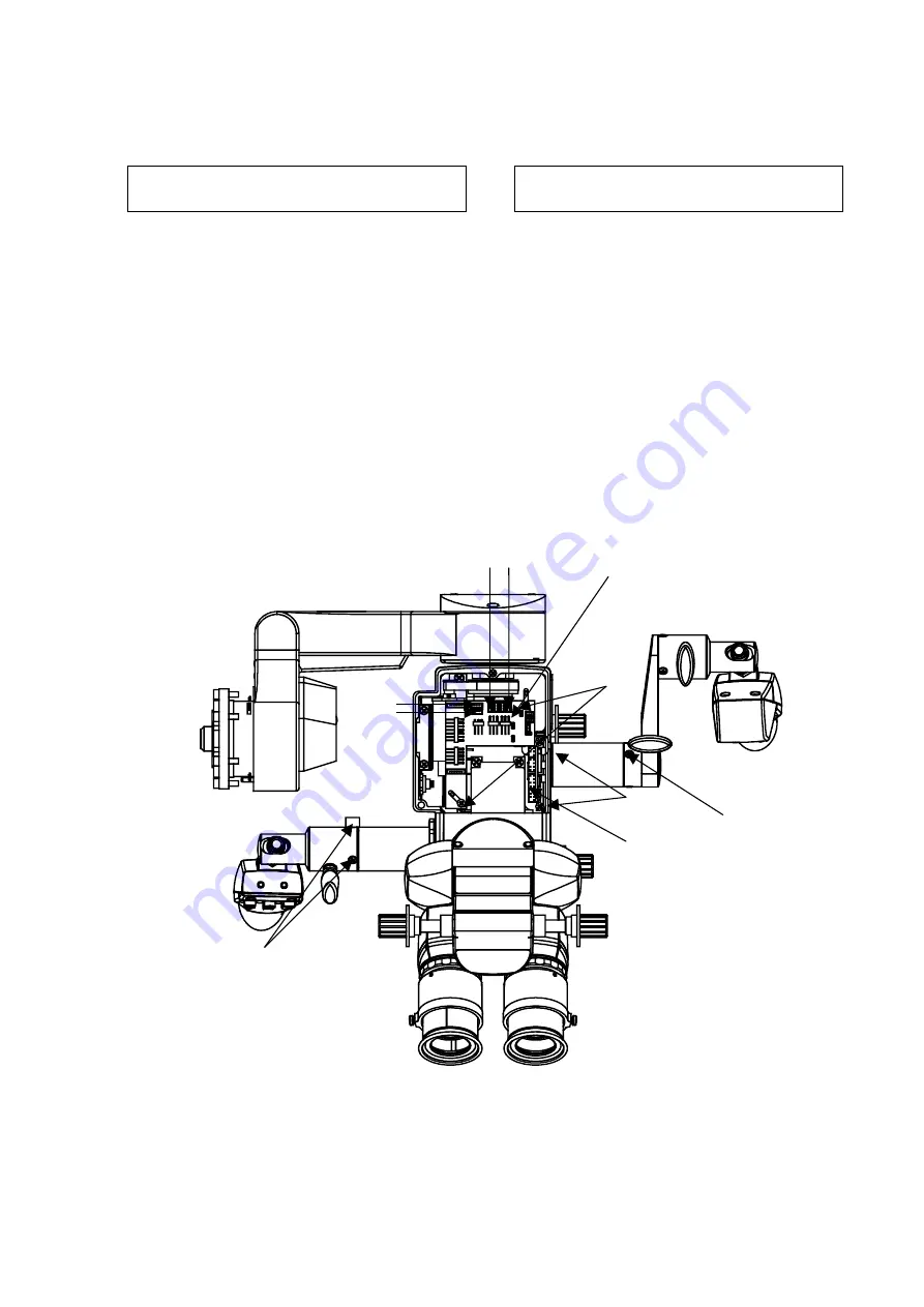
5.16 Handschalter rechts
Achtung!
Vor Öffnen des Geräts System
ausschalten und Netzstecker ziehen.
!
Deckel (1-6) öffnen.
!
Den Stecker (A4-X14) von der
Verteilerleiterplatte (11-1) abziehen.
!
Die Befestigungsschrauben (11-6) der
Verteilerleiterplatte herausdrehen.
!
Das Kabel aus dem Gehäuse ziehen.
!
Den Handschalter mit den 3 Befestigungs-
schrauben (11-5) vom Sensor abschrauben.
!
Der Einbau erfolgt in umgekehrter Reihenfolge.
!
3 Schrauben (11-5) mit Loctite sichern.
!
Der Schirmanschluss wird mit unter die
Befestigungsschraube der Verteilerleiterplatte
(11-1) geschraubt.
5.16 Handle right
Attention!
Prior to open the unit, switch off the
system and pull off the mains plug.
!
Open the cover (1-6).
!
Pull off the plug (A4-X14) from the distribution
PCB)(11-1).
!
Remove the fixing screw (11-6) from the
distribution PCB.
!
Pull off the cable from the housing.
!
Remove the handle with the 3 fixing screws
(11-5) from the sensor.
!
The installation is performed vice versa.
!
Secure 3 screws (11-5) with Loctite.
!
The shield connection has to be screws under
the fixing screw of the distribution PCB (11-1).
11-2
11-3
11-5
11-1
X11
X14
X8
X9
11-4
11-6
Summary of Contents for Hi-R 1000
Page 11: ...656 952 a 11...
Page 22: ...22 656 952 a 11 2 11 3 11 5 11 1 X11 X14 X8 X9 11 4 11 6...
Page 24: ...24 656 952 a 11 2 11 3 11 5 11 1 X11 X14 X8 X 9 11 4 11 6 2 1 12 3 12 2 12 1 X...
Page 25: ......
Page 26: ...26 656 952 a...
Page 30: ...656 952 a 31 4 1 4 2 4 4 4 3...
Page 40: ...40 656 952 a...
Page 41: ...656 952 a 41...
Page 42: ...42 656 952 a...
Page 43: ...656 952 a 43...
Page 44: ...44 656 952 a...
Page 45: ...656 952 a 45...
Page 46: ...46 656 952 a...
Page 47: ...656 952 a 47...
Page 48: ...48 656 952 a...
Page 49: ...656 952 a 49...
Page 50: ...50 656 952 a 1 4 1 3 1 2 1 5 1 1 1 6...
Page 51: ...656 952 a 51 Y 3 1 3 2 3 3 3 4 3 5 10 4 10 1 10 10 10 10 10 2 10 3 10 8 10 6 10 5 10 7 10 9...
Page 52: ...52 656 952 a...


