Hand Crimp Tool for 2.50mm (.098”) Wire-to-Board Crimp Terminals
Doc No: ATS-6382375HM
Release Date: 09-27-10
UNCONTROLLED COPY
Page 2 of 7
Revision: B
Revision Date: 10-14-10
▲
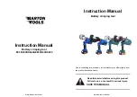
Insulation Crimp Note
:
Due to the terminal’s insulation grip design and/or
insulation diameter range, this tool uses “overlap” form
geometry in the insulation punch. This produces an
overlap insulation crimp (A620 – compliant). While the
insulation punch profile may appear “lopsided”, this is a
normal condition for this tool. See figure to the right.
(Some tools with multiple crimp pockets may not have
the “overlap” profile on all pockets).
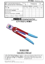
CRIMP SPECIFICATIONS:
Terminal Series No.
Bell mouth
Conductor Brush
Bend up Bend Down Twist Roll
mm
In.
mm
In.
Degree
Degree
50752
0.05-0.40 .002-.016 0.00-0.60 .000-.023
3
3
3
6
After crimping, the crimp profiles should measure the following.
Terminal
Order No.
Wire Size
Conductor Crimp
Insulation Crimp
Pull Force
Minimum
Profile
Height (Ref)
Width (Ref) Height (Ref) Width (Ref)
AWG mm
2
mm
In.
mm
In.
mm
In.
mm
In.
N
Lb. 22 24 26 28
50752
22 0.35 0.84-0.89 .033-.035 1.20 .047
1.8
.071 1.80 .071 39.2 8.8 X
24 0.20 0.76-0.81 .030-.032 1.20 .047
1.8
.071 1.80 .071 29.4 6.6 X
26 0.12 0.71-0.76 .028-.030 1.20 .047
1.7
.067 1.80 .071 19.6 4.4
X
28 0.08 0.67-0.72 .026-.028 1.20 .047
1.7
.067 1.80 .071
9.8
2.2
X
To Achieve IPC-A-620 Class 3 Crimps, the following over-all wire insulation diameter ranges are recommended:
Profile 22: 1.50-1.65mm (.059-.065”)
Profile 24: 1.30-1.50mm (.051-.059”)
Profile 26: 1.20-1.40mm (.047-.055”)
Profile 28: 1.20-1.30mm (.047-.051”)
■
Tool Qualification Notes
:
1.
Pull Force should be measured with no
influence from the insulation crimp.
2.
The above specifications are guidelines
to an optimum crimp.
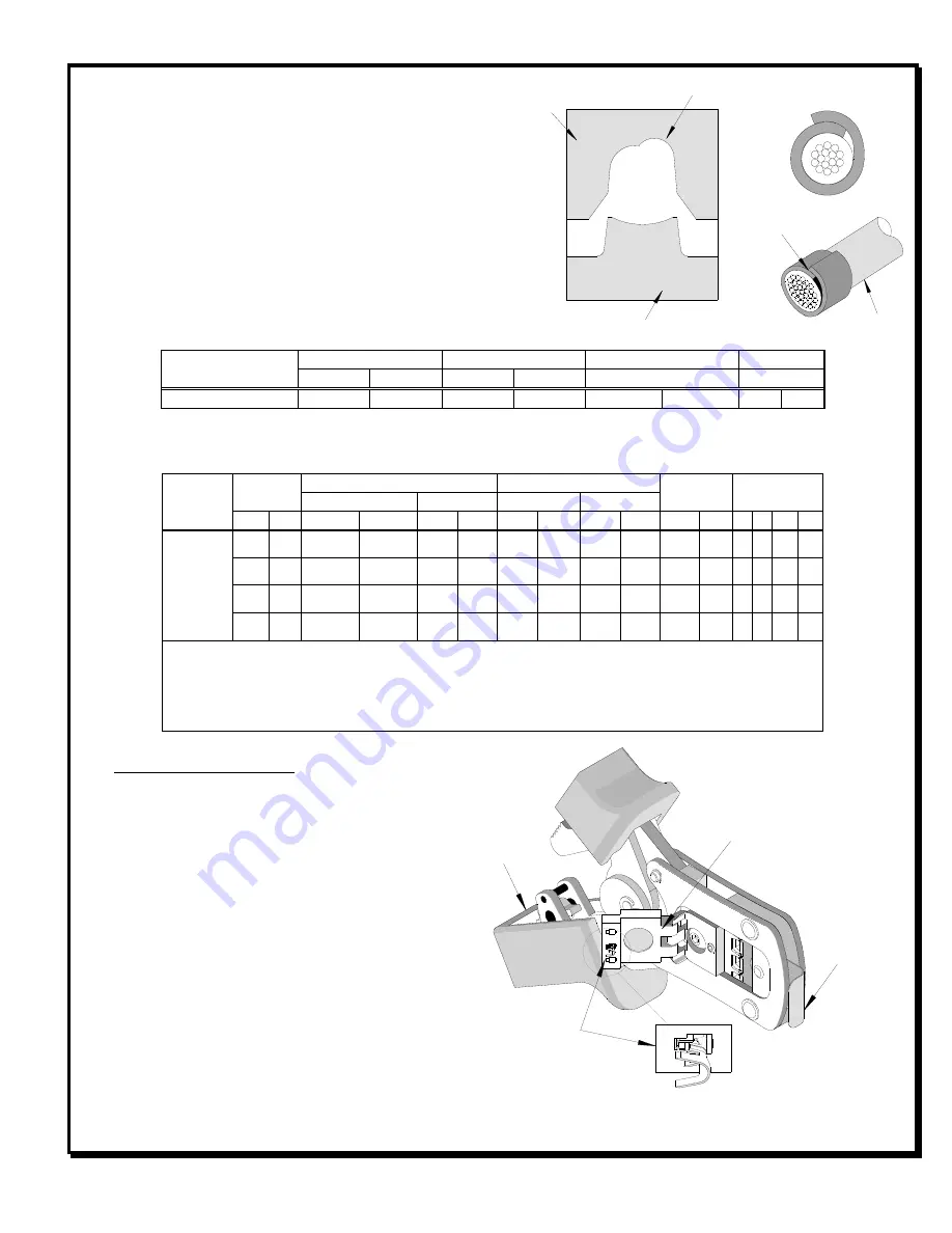
OPERATION
Open the tool by squeezing the handles
together, at the end of the closing stroke, the
ratchet mechanism will release the handles, and
the hand tool will spring open.
1.
With the hand tool in the open position, pivot
the terminal locator open by pulling up on
the locator knob and lift the wire stop blade
up. See Figure 1.
TERMINAL
SEATED IN
LOCATOR
SWING
LOCATOR
OPEN
Figure 1
HAND TOOL
OPEN
WIRE
STOP BLADE
OVERLAP
INSULATION
CRIMP
OVERLAP FORM GEOMETRY
ANVIL
PUNCH
WIRE