background image

8

MoJack EZ Max Lift

Assembly Instructions

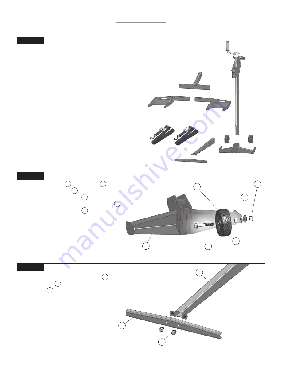
STEP 1

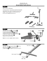
Remove lift from package.

Inventory items to be certain all parts and hardware  
are present. If any parts or hardware are missing,  
please contact MoJack at 1-877-575-3173 or  
email us at [email protected].

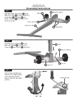
Base Support Channel 5

Base Floor Tube 3

Flange Bolts 12

STEP 3

5

Assemble the Base Support Channel       to the  
Base Floor Tube      by inserting the two  
Flange Bolts       and tighten with 12mm wrench.

3

12

STEP 2

Assemble the Wheel       to the Base  
by inserting Flange Bolt       through the 
wheel and threading the Nut      . Insert 
Flange Bolt through the Base, add Washer       
and secure with Nylock Nut       .
Repeat with second Wheel.

Note:

 Do not over tighten Nylon Lock Nut.

Base 4

Wheel 8

Flange Bolt 11

Washer 14

Nut 15

Nylock Nut 13

8

4

11

15

14

13

Summary of Contents for EZ Max 45001

Page 1: ...Ver 092718 Instructions for Assembly and Operation Instrucciones Para El Montaje Y La Operación Model 45001 ...

Page 2: ...ong the life of your lift and promote safe operation If additional information is needed or should you require a trained service mechanic contact your authorized MoJack equipment dealer or distributor or call MoJack at 1 877 575 3173 All MoJack parts are thoroughly tested and inspected before leaving the factory to ensure that they comply with all relevant safety standards NOTE Please save this ma...

Page 3: ...ile using the mower lift Do not exceed the lifting capacity of 500 lbs 226 kg front end weight If you have a question regarding weight of your machine please contact the manufacturer at 1 877 575 3173 or a local MoJack Dealer If the lift Tower is leaning while lifting or lowering the mower this indicates an overload condition REMOVE THE MOWER IMMEDIATELY Tower must be secured in place with the Tow...

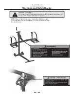
Page 4: ...arts and components sourced from suppliers that is not reproduced in this instruction manual CAUTION Avoid injury This symbol and text highlight potential hazards or death to the operator or bystanders that may occur if the hazards or procedures are ignored Warnings and Safety Decals ...

Page 5: ...y defective part within the coverage period at no charge How can I get service In order to be eligible for service under this warranty you MUST register your jack within thirty 30 days of purchasing You must keep your receipt as proof of date of sale You can register your new jack on our website at www themojack com or by calling our toll free number 1 877 575 3173 How do I contact MoJack about a ...

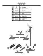
Page 6: ...o Qty Description Tower Assembly Lift Arm Base Floor Tube Base Base Support Channel Wheel Pad Safety Strap Wheels 509 0014 509 0026 509 0033 509 0048 509 0036 509 0039 009 0007 010 0013 6 7 1 1 1 1 1 2 2 2 Item No 1 2 3 4 6 3 8 2 1 6 7 7 4 8 8 ...

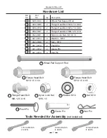
Page 7: ... Nylon Lock Nut M10 1 5 10 Flange Head Bolt M10 1 5 X 60 18 Hair Pin 14 Washer M10 14 15 Nut M10 11 Flange Head Bolt M10 1 5 X 65 18 15 Wheel Pad Support Rod Flange Head Bolt M10 1 5 X 60 Flange Head Bolt M10 1 5 X 65 Flange Head Bolt M8 1 25 X 16 Nylon Lock Nut M10 1 5 Washer M10 Nut M10 Push Pin Clevis Pin Hair Pin 509 0040 003 0005 003 0016 003 0007 002 0001 001 0014 002 0008 001 0013 001 0012 ...

Page 8: ...Floor Tube 3 Flange Bolts 12 STEP 3 5 Assemble the Base Support Channel to the Base Floor Tube by inserting the two Flange Bolts and tighten with 12mm wrench 3 12 STEP 2 Assemble the Wheel to the Base by inserting Flange Bolt through the wheel and threading the Nut Insert Flange Bolt through the Base add Washer and secure with Nylock Nut Repeat with second Wheel Note Do not over tighten Nylon Lock...

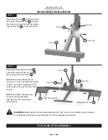
Page 9: ... the Tower Assembly to the Base with Wheels and affix with Clevis Pin and Hair Pin as shown 1 4 17 18 Tower 1 Clevis Pin 17 Hair Pin 18 Base with Wheels 4 Locked Position STEP 6 Push in side of handle and rotate from storage position to the operating position Allow to seat into the locked position STEP 4 4 10 3 14 Nylon Lock Nuts 13 Base Floor Tube 3 Flange Bolts 10 Base with Wheels 4 Washer 14 13...

Page 10: ...8 Slide the Wheel Pad Lift Arms onto both sides of the Lift Arm and secure with Push Pins NOTE The Wheel Pads can be moved in or out to fit different mower widths Use the configuration that works best with your model of lawn mower NOTE The Safety Straps must be used during operation see Step 9 of the Operating Instructions 6 2 16 Push Pin 16 WARNING Wheel pads must be equal distance from the Lift ...

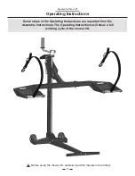
Page 11: ...uctions Before using the mower lift carefully read this manual in its entirety Some steps of the Operating Instructions are repeated from the Assembly Instructions The Operating Instructions will show a full working cycle of the mower lift ...

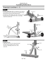
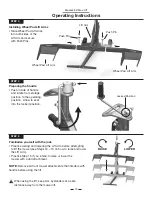
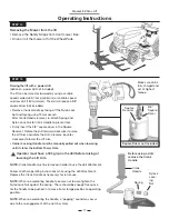
Page 12: ... insert the Clevis Pin through the hole in Carrier and lock by fastening the Hair Pin to the Clevis Pin Clevis Pin Hair Pin Tower Unfolding the Mower Lift if not applicable skip to Step 2 Remove Hair Pin and Clevis Pin from the Wheel Frame Remove the Tower out of the Wheel Frame Rotate Tower 180 degrees and insert into Wheel Frame Secure the Tower to the Wheel Frame by inserting Clevis Pin and Hai...

Page 13: ...ion Allow to seat into the locked position Wheel Pad Lift Arm Locked Position STEP 5 Familiarize yourself with the jack Practice raising and lowering the Lift Arm before attempting to lift the mower see Steps 10 13 on how to raise and lower the Lift Arm Practice Step 15 if you intend to raise or lower the mower with a drill attachment NOTE Remove all front mower attachments that interfere with han...

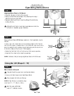
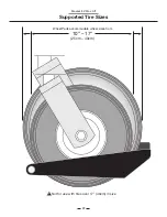
Page 14: ...Stop engine and remove the key NOTE Wheel Pads accommodate wheel sizes from 10 17 25cm 43cm Not for use with tires over 17 43cm in size STEP 7 Reverse Front Tires of ZTR Mower optional if not applicable skip to Step 8 In some cases the mower deck or anti scalping wheels will hit the Lift Arm while the mower is being raised This is often the case if part of the deck including the anti scalping whee...

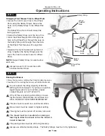
Page 15: ...fting capacity of 500 lbs 226 kg front end weight If you have a question regarding weight of your machine please contact MoJack at 1 877 575 3173 Mower deck must be raised to highest setting Strapping Front Mower Tires to Wheel Pads Secure the front mower tires to the Wheel Pads using the Safety Straps Secure the hook on the Safety Strap to the Wheel Pad Slot The Safety Strap hook should always be...

Page 16: ...ing brake on the mower The Carrier Locking Handle must be locked into one of the two Tower Holes Wheel Chock Tower Holes Carrier Locking Handle STEP 11 Raising Lift Arm to Locking Position Raise the Lift Arm until the Carrier Locking Handle drops into one of the three Tower Holes The Tower Locking Holes are the automatic safety engagement system The Carrier Locking Handle automatically drops into ...

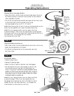
Page 17: ...rier Locking Handle must be manually pulled out when lowering until it clears the bottom Tower Hole NOTE Crank Handle must be removed in order to use the drill attachment Follow all other operating instructions while using the drill attachment Replace the Crank Handle as necessary for future use NOTE When re assembling handle take care not to over tighten the Nylon Lock Nut against the spring Ther...

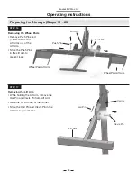
Page 18: ...in from Lift Arm Slide the Lift Arm out of the Carrier Store the Hair Pin and Clevis Pin in the Lift Arm to prevent loss Preparing for Storage Steps 16 20 Push Pin Push Pin Lift Arm Wheel Pad Lift Arm Wheel Pad Lift Arm STEP 16 Removing the Wheel Pads Remove Push Pins and pull the Wheel Pad Lift Arms out of the Lift Arm Store the Push Pins in the Lift Arm to prevent loss ...

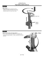
Page 19: ...h in side of handle and rotate from operating posi tion to the storage position Allow to seat into the locked position STEP 18 Raise Carrier Raise the Carrier by turning the Crank Handle clockwise until the Carrier Locking Handle drops into the top Tower Hole Top Tower Hole Carrier Locking Handle ...

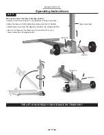
Page 20: ...emove Hair Pin and Clevis Pin from bottom of Tower Assembly Raise the Tower out of the Base by pulling up on the Lift Handle Rotate Tower Assembly 180 degrees and lower into storage position Secure the Tower by inserting Clevis Pin and Hair Pin to lock Tower Assembly in storage position Tower Assembly Clevis Pin Hair Pin Operating Instructions ...

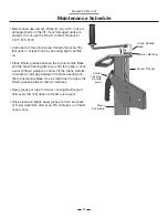
Page 21: ...se and the brass bearing after every fifty 50 uses or once a year Without weight on carrier lift the Crank Handle to create a small gap between the brass bearing and the Crank Handle Base Use a small brush to apply the lithium grease between the two surfaces Spray grease or lube in Carrier Locking Handle pivot after every fifty 50 uses or at least once a year Wipe clean and lightly apply grease to...

Page 22: ...22 MoJack EZ Max Lift Not for use with tires over 17 43cm in size Supported Tire Sizes Wheel Pads accommodate wheel sizes from 10 17 25cm 43cm ...

Page 23: ...juste y seguridad de su elevador ANTES DE USAR SU EQUIPO ELEVADOR LEA COM PLETAMENTE ESTE MANUAL Al seguir estas instrucciones de funcionamiento mantenimiento y seguridad usted aumentará la vida útil de su elevador MoJack y promoverá un funcionamiento seguro Si necesita información adicional o requiere un servicio mecánico certificado póngase en contacto con su distribuidor o concesionario de equi...

Page 24: ...odadora Nunca opere el motor mientras usa el equipo elevador No exceda la capacidad de carga de 226 kilos de peso delantero Si la torre del equipo elevador se inclina mientras se hace ascender o descender la podadora esto indica una sobrecarga Retire la podadora inmediatamente La torre debe asegurarse en su sitio con el pasador de horquilla de la misma antes de usar el equipo elevador El asa de bl...

Page 25: ...rocedentes de proveedores que no se reproducen en este manual de instrucciones PRECAUCIÓN Evitar lesiones Este símbolo y el texto de relieve los peligros potenciales o la muerte al operador oa otras personas que puedan ocurrir si se tienen en cuenta los riesgos o procedimientos Advertencias y Calcomanías de Seguridad ...

Page 26: ...cidentes o negligencia Esta garantía no cubre los daños incidentales o consecuentes Cuál es el periodo de cobertura Garantía de dos años para uso doméstico y de un año para uso comercial contados a partir de la fecha de compra por parte del propietario original Qué hará MoJack para corregir los problemas Cambiaremos cualquier parte defectuosa dentro del periodo de cobertura sin ningún costo Cómo s...

Page 27: ...ro de artículo 5 5 Conjunto de la torre Brazo de carga Tubo del piso de la base Base Canal de soporte de la base Plataforma para ruedas Tirante de seguridad Rueda 509 0014 509 0026 509 0033 509 0048 509 0036 509 0039 009 0007 010 0013 6 7 1 1 1 1 1 2 2 2 1 2 3 4 6 3 8 2 1 6 7 7 4 8 8 ...

Page 28: ... Pasador estándar 14 Arandela M10 14 15 Tuerca M10 11 Perno de cabeza con reborde M10 1 5 X 65 18 15 Varilla de soporte Perno de cabeza con reborde M10 1 5 X 60 Perno de cabeza con reborde M10 1 5 X 65 Perno de cabeza con reborde M8 1 25 X 16 Contratuerca de nylon con M10 1 5 Arandela M10 Tuerca M10 Pasador de empuje Pasador de horquilla Pasador estándar 509 0040 003 0005 003 0016 003 0007 002 000...

Page 29: ...ue Revise la lista de partes para asegurarse de que se encuentren todos los herrajes y piezas Si faltan piezas o herrajes póngase en contacto con MoJack llamando al 1 877 575 3173 o escríbanos al correo electrónico parts themojack com Ensamble el canal de soporte de la base al tubo del piso de la base mediante la inserción de dos pernos con reborde y apriete con la llave de 13 mm Canal de soporte ...

Page 30: ...4 Posición Asegurada PASO 6 Empuje en el lado de la manija y gire desde la posición de almacenamiento hasta la posición de operación Permita que se asiente en la posición asegurada PASO 4 Ensamble la base con ruedas en el tubo del piso de la base mediante la inserción de dos pernos con Arandela y las contratuercas de nylon y apriete con las llaves de 17 mm 4 10 3 13 Contratuerca de nylon con 13 Tu...

Page 31: ...amiento véase el paso 9 de las instrucciones de funcionamiento 6 2 16 Pasador de empuje 16 ADVERTENCIA las pastillas de las ruedas deben estar a la misma distancia del brazo de elevación para mantener el equilibrio adecuado Para obtener información adicional consulte el paso 6 de las Instrucciones de funcionamiento Tope de rueda 6 PASO 7 Inserte el brazo de carga dentro de la transportadora e inse...

Page 32: ...e montaje Las instrucciones de operación mostrarán cómo operar el equipo elevador muestran cómo preparar el equipo elevador para almacenarlo y cómo hacer pasar el equipo de la posición de almacenaje a la de trabajo Instrucciones de Operación Antes de usar el equipo elevador lea este manual con cuidado y por completo ...

Page 33: ...l pasador estándar en el pasador de horquilla Pasador de horquilla Pasador estándar Torre Despliegue el ascensor del cortacésped si no aplica vaya al paso 2 Retire la horquilla y el pasador de la estructura de la rueda Retire la torre de la estructura de la rueda Gire la torre 180 grados e inserte en la estructura de la rueda Asegure la torre a la estructura de la rueda insertando la horquilla y e...

Page 34: ...encuentre insertado completamente y asegurado con pasadores dentro de la base antes de elevar su podadora Practique haciendo ascender y descender el brazo de carga antes de intentar cargar la podadora véase los pasos 10 al 13 acerca de cómo hacer ascender y descender el brazo de carga Practique el Paso 15 si intenta hacer ascender o descender la po dadora con el accesorio de taladro NOTA La manija...

Page 35: ...ren en posición invertida Deslice el equipo elevador lo más cerca posible de las ruedas Posición en reversa de la rueda Posición al frente de la rueda Alineación de las plataformas para la rueda de modo que se ajusten a la podadora Coloque las llantas delanteras de la podadora 6 pulgadas frente a las plataformas para las llantas Retire los pasadores de empuje y alinee las plataformas para las rued...

Page 36: ...illa de metal y tire del extremo de la correa para apretar las correas de seguridad en la parte superior de los neumáticos para asegurar la cortacésped a las pastillas de las ruedas NOTA Inspeccione la correa de seguridad en busca de desgaste antes de cada uso Sujete siempre los neumáticos segadoras frontales con incluidas las correas Plataforma para ruedas espacio Varilla de soporte Lazo Pasador ...

Page 37: ...anija de bloqueo de la transporta dora Preparación de la podadora para darle servicio Coloque las calzas de las llantas no incluidas detrás de las llantas posteriores de la podadora Accione el freno de estacionamiento en la podadora La manija de bloqueo de la transportadora debe asegurarse en uno de los dos orificios de la torre Calza de la llanta Elevación del brazo de carga hasta la posición de ...

Page 38: ...la izquierda para hacer descender el brazo de carga Debe tirar manualmente hacia fuera de la manija de asegu ramiento de la transportadora mientras hace descender el equipo hasta que pase el orificio inferior de la torre NOTA La palanca de manivela se debe quitar para poder usar el accesorio de taladro Siga el resto de las instrucciones de operación cuando use el accesorio de taladro Vuelva a colo...

Page 39: ... Deslice el brazo de carga hacia fuera de la transportadora Guarde el pasador estándar y el pasador de horquilla en el brazo de carga para evitar que se pierdan Pasador estándar Brazo de carga Transportadora Pasador de horquilla Pasador de empuje Tope de rueda Tope de rueda Extracción de los topes de rueda Extraiga los pasadores de empuje y retire los topes de rueda del brazo elevador Guarde los p...

Page 40: ... la posición de operación hasta la posición de almacenamiento Permita que se asiente en la posición ase gurada Elevación de la transportadora Eleve la transportadora haciendo girar la palanca de manivela hacia la derecha hasta que la manija de asegura miento de la transportadora caiga dentro del orificio de la torre Orificios de la torre Manija de bloqueo de la transporta dora ...

Page 41: ...ar y el pasador de horquilla del fondo del conjunto de la torre Eleve la torre hacia fuera de la base tirando hacia arriba la manija de elevación Gire el conjunto de la torre 180 grados y hágalo descender hasta la posición de almacenamiento Asegure la torre mediante la inserción del pasador de horquilla y el pasador estándar para asegurar el conjunto de la torre en la posición de almacenamiento Co...

Page 42: ...bronce después de cada cincuenta 50 usos o una vez al año Sin peso sobre la transportadora haga ascender la palanca de manivela para crear un hueco pequeño entre el roda miento de bronce y la base de la palanca de manivela Use un cepillo pequeño para aplicar grasa de litio entre las dos superficies Rocíe grasa o lubricante en el pivote de la manija de aseguramiento de la transportadora después de ...

Page 43: ...43 Elevador MoJack EZ Max No debe utilizarse con neumáticos de más de 43 cm 17 de tamaño Tamaños de las Llantas compatibles Las pastillas de las ruedas se ajustan a tamaños de ruedas de 25cm 43cm 10 17 ...

Page 44: ......
Reviews: