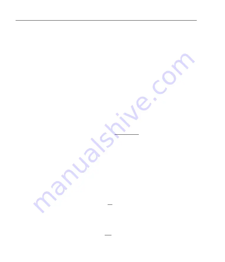
48
Appendix C. Modulation coils
where
n
is the number of turns per unit length and
i
the current. For
wire diameter 0.4 mm,
n
= 2500 m
−
1
, and the current requirement is
only 22 mA
/
MHz.
C.2
Coil impedance
However, driving an oscillating current through a coil is problematic
because the impedance grows with the frequency. The impedance
is given by
X
L
=
ωL
where
ω
is the radial frequency and
L
the
inductance. The inductance for a long solenoid is
L
=
µ
0
n
2
Al
(C.2.3)
where
A
is the cross-section area of the coil (
πr
2
for a circular cross-
section) and
l
is the coil length. In practice, the inductance will be
less (e.g. see Wheeler [9]):
L
Wheeler =
N
2
r
2
228
r
+ 254
l
(mH)
(C.2.4)
where
N
is the total number of turns,
r
is the coil radius in metres,
and
l
is the length in metres (
l >
0
.
8
r
). We have found that for
dimensions typical of coils wound around vapour cells, these two
formulae agree within a factor of two.
Note that the inductance increases with
n
2
whereas the magnetic
field and hence modulation depth grows with
n
; thus for our pur-
poses, we generally prefer small
n
and large currents. On the other
hand, the driving voltage requirement (the “back emf”) is given by
ε
=
−L
di
dt
ε
max =
Li
0
ω
(C.2.5)
for a sinusoidal current of amplitude
i
0
. The required output slew
rate is
dV /dt
=
−L
d
2
i
dt
2
Max
≡ Li
0
ω
2
.
(C.2.6)
Summary of Contents for DLC202
Page 1: ...External Cavity Diode Laser Controller Models DLC 202 DLC 252 DLC 502 Revision 6 00 ...
Page 4: ...ii ...
Page 16: ...6 Chapter 1 Introduction ...
Page 30: ...20 Chapter 2 Connections and controls ...
Page 42: ...32 Chapter 3 Operation ...
Page 62: ...52 Appendix C Modulation coils ...
Page 66: ...56 Appendix D External modulators and injection current modulation ...
Page 76: ...66 Appendix G Connector pinouts ...
Page 78: ...68 Appendix H PCB layout ...
Page 81: ......


