


01/08 AWB2190-1430GB
67
5 Motor starter RA-MO (from Version 3.0)
Device overview
Key to type references
h
Your device’s version number is printed on the nameplate,
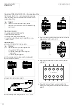
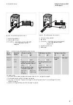
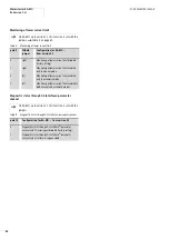
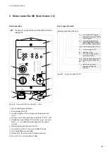
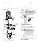
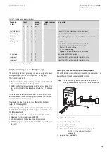
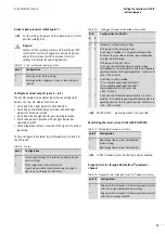
Figure 68: Overview RA-MO (here: RA-MO2.1.../C3A)
a
Space for labelling top and bottom
b
Status and diagnostic LEDs
c
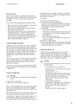
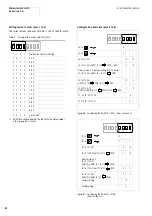
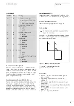
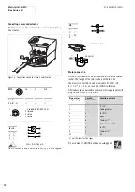
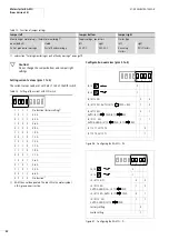
Lasering: Assignment of DIP switch position to motor protection
values
d
Locking screw: Configuration and parameterization with DIP switch
e
Two additional inputs through M12 for external sensors. For version
RA-MO…A… one additional output through M12 for external
actuators.
f
Motor output plug for motor cable SET-M3/…
g
Connection AS-Interface
®
with user-assembled M12 plug
h
User-assembled power plug (5-pole)
i
Selector swicht for clockwise and anticlockwise operation
j
Key-switch for manual and automatic mode
0,3A
1 0 1 1
0,4A
0 1 1 1
0,6A
1 0 0 0
0,8A
0 1 0 0
1,0A
1 1 0 0
1,2A
0 0 1 0
1,5A
1 0 1 0
1,7A
0 1 1 0
1,9A
1 1 1 0
2,1A
0 0 0 1
2,6A
1 0 0 1
3,6A
0 1 0 1
5,0A
1 1 0 1
6,6A
0 0 1 1
Motor Control Unit
FAULT
O3
POWER
I4
I3
REV
FWD
UV
3 AC
I
3
I
4
OFF
RESET
REVERSE
FORWARD
OFF
a
b
c
d
e
f
j
i
h
g
1
ON
2
3
4
7
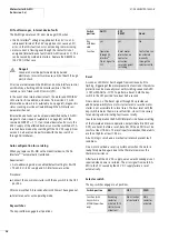
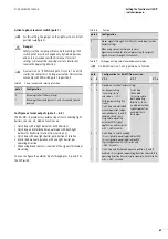
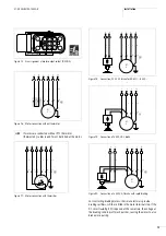
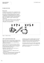
RA-MO...W
L1
⇒
T3
L3
⇒
T1
L1
⇒
T1
L3
⇒
T3
1
0
1
0
1
0
0
1
0
1
M
3
h
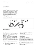
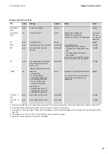
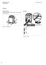
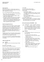
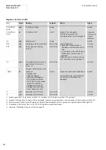
Figure 69: Key to part numbers RA-MO
RA-MO (L) (24V) - W A (230)/ C3 A
A = User-assembled M12 plug for
supply with AS-Interface
®
and 24
V auxiliary power
C3 = Power plug fordecentralized
power supply through adapter
cable; for ribbon or round cable
(230) = brake infeeding with 230 V AC
A =
1 external output via M12
W = Reversing starters
D =
DOL starter, without selector
switch REV-OFF-FWD
24 V: Contactor, power supply 24 V DC
with-
out:
Contactor, power supply 400 V
AC
L =
low function (no manual
operation, no thermistor
protection)
Summary of Contents for Rapid Link
Page 10: ...01 08 AWB2190 1430GB 6 ...
Page 40: ...01 08 AWB2190 1430GB 36 ...
Page 48: ...01 08 AWB2190 1430GB 44 ...
Page 70: ...01 08 AWB2190 1430GB 66 ...
Page 146: ...01 08 AWB2190 1430GB 142 ...
Page 162: ...01 08 AWB2190 1430GB 158 ...