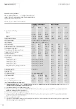


Speed controller RA-SP
01/08 AWB2190-1430GB
98
AS-Interface
®
connection
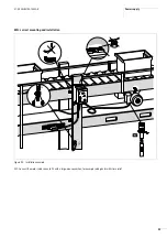
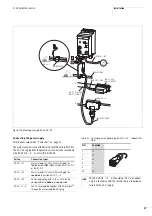
Connection through cable with M12 plugs
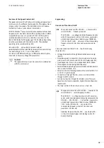
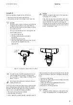
Connecting AS-Interface
®
and 24 V (RA-SP…/C…A)
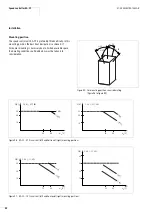
Connection through user-assembled plug M12
Before establishing the connection to AS-Interface
®
, you can
assign the AS-Interface
®
address through plug M12 with an
addressing device,
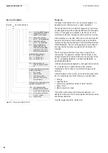
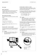
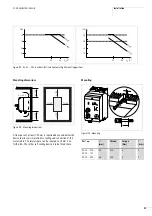
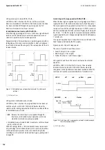
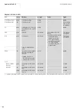
Connecting sensors (RA-SP2-34…)
RA-SP…342/343… features two M12 sockets for connecting two
sensors. To each of the M12 sockets I3 and I4 of the RA-SP-HE…
you can connect two sensors. In this case the signals must be split
through the Y-connector RA-XM12-Y.
PIN
Function
1
ASi+
2
–
3
ASi–
4
–
PIN
Function
1
ASi+
2
0 V
3
ASi–
4
24 V
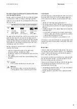
h
On M12 sockets I3 and I4 with visible nut, pin 2 is not
assigned.
On M12 sockets I3 and I4 without visible nuts, pins 2 and
4 are bridged.
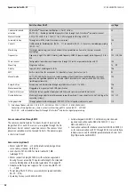
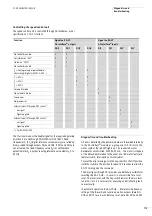
Exception: RA-SP-HE…
RA-SP2-342…
RA-SP2-343…
„A“-coded (IEC/EN 60947-5-2)
1 = brown
2 = white
3 = blue
4 = black
24 V
H
S
I
F
70 mA
RA-SP-HE-…
or
24 V
H
S
I
F
160 mA
RA-XM12-Y
I3 + I4
1
L+
2
–
3
L–
4
I
4
3
1
S
1
3
4
1
4
1
4
I3 + I4
1
L+
2
I…B
3
L–
4
I…A
1
4
3
2
S
S
1
3
4
1
3
4
1
3
2
4
1
3
2
4
1
3
2
4
1
4
1
4
1
4
1
4
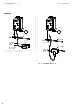
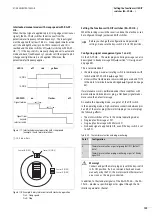
h
If you have connected 4-wire sensors to RA-SP-HE... on
which pin 2 carries, for example, a Live signal, the colours
of LED indicators I3 and I4 change;
Summary of Contents for Rapid Link
Page 10: ...01 08 AWB2190 1430GB 6 ...
Page 40: ...01 08 AWB2190 1430GB 36 ...
Page 48: ...01 08 AWB2190 1430GB 44 ...
Page 70: ...01 08 AWB2190 1430GB 66 ...
Page 146: ...01 08 AWB2190 1430GB 142 ...
Page 162: ...01 08 AWB2190 1430GB 158 ...