


5
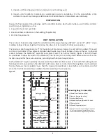
Figure 4.
Drywall Fitting
Drywall
Drywall
Acoustical
Caulk Bead
Panel Mounting
Screw
Locations
Level
ArtWorks® unit (use extreme care with screws that are close to medical gas piping or electrical conduits). Perform
all taping, joining, texturing and painting before resetting the panel trim back to its original position. Any additional
wall coverings may also be installed at this time.
IMPORTANT: Wainscoting should not be installed under the perimeter flange of the ArtWorks® unit. If the coverings
are to be installed before the tub housing, terminate 0.25" from the outer edge of the perimeter flange.
Once the wall materials are completed, caulk the perimeter of the panel trim with an acoustical sealant and
position it back against the finished wall (Figure 4). This should be the same location that the medical gas brazing
was performed to remove any tension on the brazed connections made.
Should the optional electrical console be used, the backbox will need to be adjusted approximately 1/8" under
flush with the finished wall surface. This is accomplished by adjusting the four screws (two on each side) located
on the ends of the backbox assembly. This will allow the fascia trim to be seated properly around the component
coverplates and rest firmly against the finished wall surface.
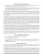
Figure 5.
Keyhole
Attachment
Slot (4x)
Counterweights
installed behind panel
(5 each side, 10 lb. total)
ARTWORK INSTALLATION
The outside dimensions of the framed artwork (supplied by others) are to be 30"H x 34"W. Also, the use of Plexiglas
®
glazing is required in order to limit any problems with the weight of the artwork and frame.
Attach the back of the artwork to the aluminum adapter plate, using screws provided. The total allowable weight
for the framed artwork and adapter plate is 12 pounds. A wide range of framing options is accommodated by the
addition or removal of counterweights (1 lb. each) located on the back side of the movable steel panel (Figure 5).
For example, if the combined weight of the framed artwork and aluminum adapter plate is eight pounds, remove
all but four of the counterweights (leaving two on each side). If the weight of the artwork and adapter plate is 12
pounds, remove all the counterweights.
The lifting mechanism is under compression when the artwork is in
the lowered position and assists to counterbalance the weight. If the
compression is too great, the picture will have a tendency to ride up
without assistance; if it is too low, operation of the mechanism will be
more difficult.
The back side of the adapter plate has four shoulder rivets, one at each
corner. To attach the artwork assembly to the moveable steel panel,
tilt the top of the artwork back slightly and engage the upper shoulder
rivets on the adapter plate into the upper keyhole attachment slots
on the steel panel (Figure 5). Slide the artwork assembly down into
the keyhole slots, engaging the lower shoulder rivets into the lower
keyhole slots as the artwork is lowered into position. Check to see that
the artwork is level and secure it in place by installing two locking
brackets (provided) at the top corners of the moveable panel.