5-565.1
19
oPtions
b) Two-stage Electronic Type Thermostat - Includes a
factory installed discharge air sensor. The thermostat
body is field installed remotely and includes the discharge
air set point adjuster that must be field set. Refer to
Literature 5-577 latest revision.
figure 19.1 - two-stage electronic type thermostat sensor
c
) Mechanical Modulating Sensing Bulb - The mechanical
modulating valve includes a hydrostatic sensing bulb that
is factory installed in the discharge air stream for cooling
package units. For blower package units the sensing
bulb is temporarilly afixed to the side of unit to be field
installation in duct work. The discharge air temperature
is field set by the control dial on the modulating gas
valve. Refer to Control Operating Sequence - Mechanical
Modulating Gas Controls for set point temperatures.
figure 19.2 - mechanical modulating sensing Bulb
d)
Electronic Modulating Discharge Air Thermostat –
Includes a factory installed mixing tube and discharge
air sensor for cooling package units. For blower package
units, the air sensor is factory wired but field installed in
duct work. The set point adjuster is field installed remotely
and must be field set. Refer to Literature 5-578 latest
revision.
figure 19.3 - electronic modulating discharge air
thermostat
(2) low gas Pressure switch – (oPt)
The low gas pressure switch is factory installed in the duct
furnace above the gas train. The switch monitors the gas
pressure upstream of all the gas controls and shuts off the
electric supply to the ignition controller and combination gas
valve if low gas pressure is experienced. This will shut off all
gas flow to the burner. The switch has an automatic reset so
that if the gas pressure is interrupted and then is returned, the
switch will automatically allow the unit to operate when gas
conditions are returned to the allowable range of the pressure
switch. The pressure switch range is 2" to 14" W.C. and should
be set to insure that the minimum inlet gas pressure is available
(6" W.C. for natural gas, 11" W.C. for propane gas).
figure 19.4 - low or High gas Pressure switch
(3) High gas Pressure switch – (oPt)
The high gas pressure switch is factory installed in the duct
furnace above the gas train. The switch monitors the gas
pressure downstream of all the gas controls and shuts off
the electric supply to the ignition controller and combination
gas valve if high gas pressure is experienced right before the
manifold. This will shut off all gas flow to the burner. The switch
has a
manual reset so that if the gas pressure is too high, a
service person must check the unit to make sure that none of
the gas controls have been damaged by the high gas pressure
and then reset the switch to allow the unit to operate when gas
conditions are returned to the allowable range of the pressure
switch. The pressure switch range is 2" to 16" W.C. and should
be set to insure that the maximum manifold gas pressure is not
exceeded (3.5" W.C. for natural gas, 10" W.C. for propane gas).
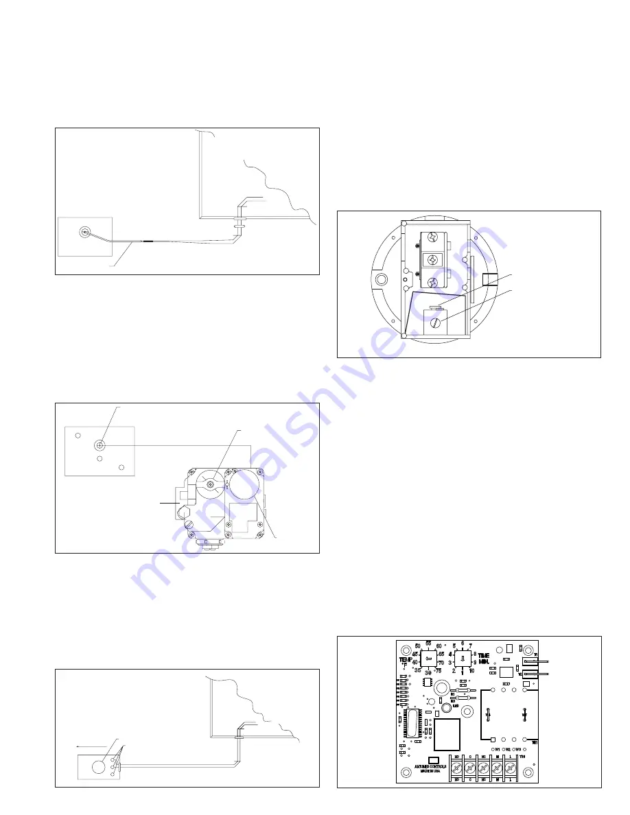
(5) timed freeze Protection – (oPt)
The timed freeze protection system is factory installed in the
duct furnace electrical junction box with the sensor (30°-75°F
adjustable) factory installed in the discharge air stream. On
initial start-up, the timed delay in the system allows the unit to
go through the normal ignition sequence. The timed delay is an
automatic reset switch and adjustable for 1-10 minutes. In the
event that the unit fails to fire after this period, the discharge air
sensor will sense the cold air and will shut down the entire unit.
Duct Furnace
Electrical
Control
Box
Air flow
3
2
1
Mixing Tube
Discharge air
Sensor Terminals
Gas Control Knob
Hydrostatic Sensing Bulb
HI 8 7 6
5
4
3
2
1
LO
IN
OFF
NO
Control Dial
Hydrostatic Sensing Bulb
Gas Control Knob
Control Dial
Box
Control
Electrical
Duct Furnace
Sensor
Duct
Furnace
Electrical
Control
Box
Sensor
Pressure adjustment screw
(High Pressure Switch only)
Reset Switch
C
NO
NC
Top: cover removed
Pressure adjustment screw
Reset Switch
(High Pressure Switch only)
Top cover removed
figure 19.5 - timed freeze Protection module


