7
ATH15-501.0 (
Supplement to ATH15-500.10
)
D-
CA
BI
NE
T
SI
ZE
U
NI
T
(O
VE
R
80
0,
00
0
BT
U/
HR
)
D-
CA
BI
NE
T
SI
ZE
U
NI
T
(U
P
TO
8
00
,0
00
B
TU
/H
R)
C-
CA
BI
NE
T
SI
ZE
U
NI
T
(A
LL
G
AS
H
EA
T
SI
ZE
S)
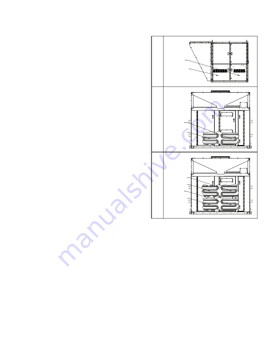
SECONDARY A
SECONDARY C
SECONDARY B
PRIMARY
SECONDARY A
PRIMARY
SECONDARY A
PRIMARY
Figure 7.1 - Furnace Primary/Secondary Locations
Furnace locations are shown for reference, not the location of the furnace
controls. Refer to the figures on pages 11 through 15 for controls location.
Single and Two Stage Furnace / Manifold Section
(applies to C- and D-Cabinet units only)
The following steps are required to check/adjust the manifold
pressure on the combination gas valve for staged furnaces
(multiple furnace units only).
1. With supply pressure set as described in the sections
above, manually set the unit demand at 10.0 vDC for the
furnace being tested as described in the “Carel Controller
Settings” section on page 4.
2. On split manifold units (furnace model digit 11=B, C, or D),
verify that the combination valve on fixed input portion of the
manifold supplies a pressure of 3.5 +/- 0.2”WC for Natural
Gas (10.0+/- 0.2”WC for LP) on the outlet of the valve when
all burners are operating.
3. On heat exchangers with two stage controls (C and
D-Cabinet units up to 800MBH):
a. Reduce the heat demand until the non-modulated furnace
is operating at low input. This will typically occur between
50 and 75% demand. The easiest way is to drive Furnace
2 to low fire by following step 17 on page 4.
b. Verify that the combination valve supplies a manifold
pressure of 1.0 +/- 0.2”WC for Natural Gas (2.5+/-
0.2”WC for LP) on the outlet of the valve when all
burners are operating at reduced demand.
4. On heat exchangers with single stage controls (D-Cabinet
units 900MBH and larger), verify that the combination valve
supplies a manifold pressure of 3.5 +/- 0.2”WC for Natural
Gas (10.0+/- 0.2”WC for LP) on the outlet of the valve when
all burners are operating at full demand.
5. Once the setting of the valve(s) has been completed, move
the field installed manual shut-off valve to the “OFF” position,
remove the manometer, and replace the 1/8" pipe plug.
6.
After the plug is in place, move the field installed manual
shut-off valve to the “ON” position and recheck all pipe
plugs for gas leaks with soap solution.
Clearing Furnace Control Board Error Codes
1. Error codes on the primary control board (VB1285) can
be viewed by pressing the UP/MODE button for at least 4
seconds until the LED display changes to display “Lo9” and
release the button. Refer to Figure 5.1 for location of buttons
and LED display and Table 8.1 for a listing of error codes.
2.
Briefly press the UP/MODE button again to review the error
codes. If there are no alerts or error codes currently stored
in the history log, the display will instead revert back to the
original normal display mode. If any error codes are currently
stored in the history log, then they will be displayed beginning
with the most recently recorded. The UP/MODE and DN/
SELECT buttons will navigate through the log.
3. To clear the error codes from memory, press the DN/
SELECT button until “CLr” is displayed. Press and hold the
DN/SELECT button for 4 seconds to clear the memory. The
board will then revert to normal operation.
4. To exit the History Log without clearing the log and revert to
normal operation depress the UP/MODE button for 4 seconds.
5. On the secondary staged control boards (United
Technologies), refer to the LED indicator and Tables 9.1 and
9.2 for a listing of error codes.
Final Check
1. Operate furnace (all furnaces for units with multiple heat
exchangers) at high fire and verify that gas pressure to the
INLET of the combination gas control valve is maintained
at 6”-7” W.C. on natural gas (11”-14” W.C. on propane (LP)
gas). If the pressure cannot be maintained while operating
at high fire, the gas supply system is undersized and must
be corrected and the entire check and adjustment of gas
pressures section must be repeated.
2. Once all gas pressures have been checked and are at
the proper settings, shut the unit down and move the field
installed manual shut-off value to the “OFF” position.
3. Remove all testing equipment and replace any hardware
(plugs, covers, etc.)
4.
After the plug is in place, move the field installed manual
shut-off valve to the “ON” position and recheck all pipe
plugs for gas leaks with soap solution.
5. Close the unit access doors.
6. Resume with instructions on page 32 of the Installation
and Service Manual, literature #ATH15-500.10.
GAS HEAT START-UP PROCEDURE


