


16
STAGE 5:
BUILDING THE ENGINE MOUNT AND PLUMBING
Preparation:
Cut two 1" lengths of WP129K-1.5 to
make the air intake tubes, then file a 106º
angle to one end of each tube. When
installed, the angled end faces out and tapers
toward the front of the airframe like an air
scoop. Cut a 1 1/2" length of WP129K-1.5
to make the engine mount tube.
Brass eyelets tend to be rolled in slightly at
the non-flanged end. Use a needle file to
straighten this out so the eyelets will slide
easily over the ends of the rear support
(CAF43). Referring to the plumbing
schematic Fig.25, drill #69 shallow holes
where indicated in parts CAF39, 40, 41,
42b and 45. Part CAF39 gets two holes,
one in the end and one where the little cast
tail is. Cut off the tail first. Finally, dry fit
the engine mount (CAF38) to the front of
the airframe. Sand and trim as needed to
get a snug fit.
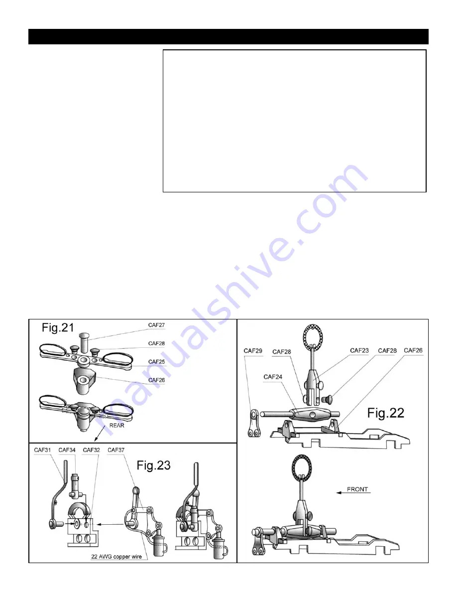
Assembly:
Glue together the parts as shown in Fig.18
with the exception of the engine mount
tube which should be left loose at this
stage. Glue this subassembly to the airframe
at former “A.” Note the placement of part
CAF42b in the channel on CAF42a.
Remove the brass tube and glue on the end
cap (CAF73). Slide this assembly through
the carburetor (CAF45), the rear support
(CAF43) and then the center hole in the
engine mount. Line up the four arms of the
rear support with the two pairs of large
holes in the diagonal mounts (CAF04),
then slide the brass eyelets (GS4-7) through
the holes to secure the support arms. Glue
the eyelets to the arms being careful not to
get any glue on the brass engine mount
tube. Slip the air intakes over the carburetor
studs, then slide the carburetor and the
tube so that the intake tubes are straight
out to the sides, just clearing the rear of the
diagonal mounts. The hole you drilled in
the carburetor casting should face straight
up. Slide the mounting tube forward so the
end cap touches the carburetor and glue
everything in place. Finally, glue the rigging
attachments (CAF48) into the small holes
on the diagonal mounts so that the rings
are vertical.
Firewall Option:
Although the kit does not include the fire-
wall, it is a simple matter to make one from
thin sheet aluminum, such as that of a flat-
tened soda can. Either trace around CAF38
or use a compass to layout a 2 11/16" disc.
Cut off the bottom to match CAF38 and
cut a 3/4" hole in the center. Glue this to
the front of CAF38.
CAF38
Engine Mount
1
Britannia casting
CAF39
Oil pump
1
Britannia casting
CAF40
Air pump
1
Britannia casting
CAF41
Magnetos
2
Britannia castings
CAF42a&b
Magneto support
1
each Britannia casting
CAF43
Rear support
1
Britannia casting
CAF44
Manual starter
1
Britannia casting
CAF45
Carburetor
1
Britannia casting
WP129K-1.5
Air intakes
2
3/16" x 1" brass tube
WP2841
Rear support connectors
4
.219" x .121" brass eyelets
CAF48
Rigging attachments
2
Britannia castings
WP129K-1.5
Engine mount tube
1
3/16" x 1 1/2" brass tube
CAF73
Engine tube end cap
1
Britannia casting
Parts List For Stage 5
Camel_instructions.qxd 9/13/06 1:34 PM Page 16
Summary of Contents for SOPWITH CAMEL F.1
Page 6: ...6 ...
Page 10: ...10 ...
Page 11: ...11 ...
Page 14: ...14 ...
Page 15: ...15 ...
Page 21: ...21 ...
Page 22: ...22 ...
Page 24: ...24 Lower Wings ...
Page 25: ...25 Wing Tip ...
Page 27: ...27 COLOR PHOTOS CAN BE VIEWED ON OUR WEBSITE WWW MODELEXPO ONLINE COM ...


