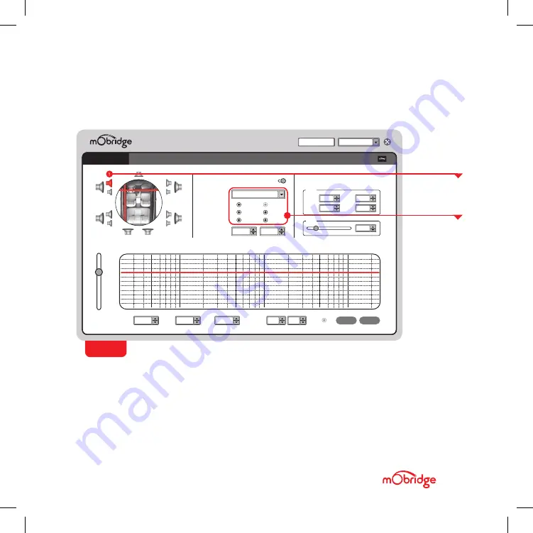
This configuration screen will allow you to
configure the channels for the correct mapping of
your particular system.
First select a speaker from the image of the
vehicle in the top left corner, then select an
output mapping from the drop-down menu in the
middle of the screen to select the channel output
you have connected for that particular speaker.
Repeat this for each speaker and its corresponding
output channel.
When running a component speaker system with
a passive crossover, only select one of the
speakers in the cluster. It is not important which
speaker is chosen, as this is only the mapping
stage. Crossover settings will allow for correct
settings for this type of speaker system.
C H A N N E L E Q
C O N N E C T E D
0.00Hz
Default
Preset 01
DELETE
CLEAR
FREQ
0.00Hz
0.00Hz
MAG
0.00Hz
0.00dB
GAIN
0.00Hz
0dB
Q-FACTOR
0.00H
0.01
0.00Hz
0.01
Q-L/R
C O N F I G U R A T I O N
12dB
50Hz
100Hz
500Hz
1KHz
10KHz
5KHz
20KHz
6dB
0dB
-6dB
-12dB
-18dB
-24dB
0.00Hz
Output Channel 1
Output Mapping
Time Alignment
Input Mapping
Left
Right
Sink 1
Sink 2
Sink 3
Sink 4
0.00ms
0.00ms
MONO INPUTS
Sink 1
Sink 2
0.00Hz
0 dB
0.00Hz
0 dB
Sink 3
Sink 4
0.00Hz
0 dB
0.00Hz
0 dB
Gains
1
3
5
11
7
9
10
2
4
5
12
8
0.00Hz
1.4 ms
Delay
MUTE
FRONT LEFT TWEETER
FIG 03
Configuration Page
CONFIGURATION
SETTINGS
SELECTED
SPEAKER
SPEAKER MAPPING
Once the DA-G2 MOST150 unit is connected to the mObridge DSP application, you will see the below
screen
(FIG 03)
.
D A - G 2 M O S T 1 5 0 O P T I C A L M E R C E D E S
/ /
G U I D E
PA G E 1 5
Summary of Contents for DA-G2 MOST150
Page 2: ......
Page 19: ......
Page 20: ...M O B R I D G E U S CONTACT US PHONE 61 3 9465 5997 INQUIRIES sales mobridge com au ...


