


4. Using the
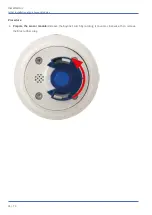
and the two pre-mounted screws (highlighted red in the figure), fixate
the connector box on the mounting plate.
Fig. 17: Mounting the connector box (top view) using the two screws (highlighted red in the figure) on the mounting
plate.
Caution: Make sure that the connector box is properly fastened on the mounting plate as shown
above. Failing to do so could damage the mainboard of the camera!
Continue with
Finishing the Installation of the Camera, p. 48
Installation
Connecting the Camera
47 / 74
Summary of Contents for MOBOTIX M73
Page 1: ...Schnellinstallation MOBOTIX M73 2019 MOBOTIX AG ...
Page 4: ......
Page 6: ......
Page 16: ......
Page 19: ...19 74 Delivered Parts and Dimensions 9 ...
Page 24: ...Delivered Parts and Dimensions M73 Dimensions Fig 5 Fig 6 M73 Dimensions Side View 24 74 ...
Page 25: ...25 74 Technical Specifications 10 ...
Page 43: ...Fig 12 Mounting plate installed on wall Installation Mounting Options 43 74 ...
Page 51: ...Fig 18 Properly installed M73 Installation Finishing the Installation of the Camera 51 74 ...
Page 52: ......
Page 70: ......