background image


Attention! Very important 
 

This  user  manual  contains  important  guidelines  for  the  installation  and  usage  of  the 
Mobeye


MS100E.  Please  read  these  thoroughly  before  you  start  using  the  Mobeye


MS100E! 
In case of damage caused by disregarding the guidelines, the warranty becomes void.  
The  user  must  regularly  check  the  proper  functioning  of  the  Mobeye  MS100E.  The 
manufacturer cannot be held liable for any  damage or loss caused by any incorrect use 
or incorrect functioning of the Mobeye


MS100E. 


Safety guidelines 

•  The permitted ambient temperature during operation may not be exceeded (not lower 

than -10°C and not higher than 55°C). 

•  The device is intended for use in dry and clean places. 
•  Protect the device from moisture, heat and water splashing. Not intended for external 

use. 

•  The guidelines for the battery usage must be regarded.  
•  Do not expose the device to strong vibrations. 
•  Do not let it fall from height. 
•  Do  not  use  in  an  environment  where  any  inflammable  gases,  vapours  or  dust  are 

present or could be present.  

•  Repair of the device may only be carried out by people, trained for Mobeye

®

 repair. 

•  If the device must be repaired,  only  original replacement components may be used. 

The use of different parts may lead to damage of the Mobeye MS100E. 

 
Use in accordance with the regulations 

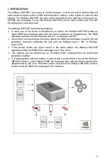
The purpose of this device in accordance with the regulations is the generation of SMS 
text  messages  and  telephone  calls  after  the  activation  of  one  of  the  inputs,  or  after  an 
internal  trigger;  switching  the  outputs  after  an  alarm  or  via  incoming  call/SMS.  Other 
uses are not permitted. 
 

Battery recycling 

The lithium-ion battery, which is an accessory for the Mobeye MS100E can be recycled. 
Please take empty batteries to a nearest collection point. 

Summary of Contents for MS100E

Page 1: ...Installation manual Mobeye MS100E GSM Measure Control and Alarm module SW version 7 n...

Page 2: ......

Page 3: ...rnal use The guidelines for the battery usage must be regarded Do not expose the device to strong vibrations Do not let it fall from height Do not use in an environment where any inflammable gases vap...

Page 4: ......

Page 5: ...tomatic time based arm disarm 8 5 8 identification text 9 5 9 Alarm text 9 5 10 Input type 9 5 11 Input delay time 9 5 12 Inactive time 9 5 13 Power failure delay time 9 5 14 Authorisations and remote...

Page 6: ...programmed The SMS message contains the text Mobeye alarm 1 or Mobeye alarm 2 As soon as the inputs leave the alarm status an SMS text message is sent to the set telephone numbers containing the text...

Page 7: ...e a month Open the back cover Insert the SIM card in the holder For opening closing move the cover slightly 2 2 CONNECT A SENSOR Open the hole in the enclosure and insert the 2 wires of an external se...

Page 8: ...falls out the unit will keep sits functions and a power failure message can be sent The GSM module remains open and the sensor inputs remain active The back up battery is able to power the module for...

Page 9: ...will send an alarm notification First an SMS text message is sent to all programmed alarm numbers next a phone call is made to the numbers When you answer the phone a beep tone is heard Confirm using...

Page 10: ...o an external power source Please find below the architecture of the main unit Inputs External sensors can be connected to the inputs Upon closing or opening an input the Mobeye MS100E will send an al...

Page 11: ...Send an SMS message with following content The CODE stands for the installation code Factory setting is 1111 Do not forget the space between CODE and COMMAND The complete scheme with SMS commands is...

Page 12: ...he unit will only send an SMS text message as alarm notification It is not possible to switch off both the SMS and the call 5 5 INTERVAL TEST MESSAGE The Mobeye MS100E can send test messages Through t...

Page 13: ...type is set to NO 5 11 INPUT DELAY TIME The input delay time defines the time that the inputs are triggered before an alarm is initiated If the input returns to the non alarm status within the delay...

Page 14: ...on to let them be switched by any incoming call SMS without being authorised To disable the need for authorised numbers the authorization option can be set to OFF Default is ON 5 16 DURATION OF OUTPUT...

Page 15: ...puts 2 Power failure Send SMS call 3 Power restored Send SMS 4 Input 1 triggered Send SMS call 5 Input 2 triggered Send SMS call 6 Input 1 restored Send SMS 7 Input 2 restored Send SMS The SMS texts a...

Page 16: ...The unit calls the set alarm numbers The receiver will hear a 2 tone signal and can confirm by pressing 1 6 3 PROGRAMMING ACTION RULES Send following SMS commands in following format CODE TRIGGER REAC...

Page 17: ...be deleted by an SMS by the command below incl index number The index number is the sequence number of the action rule as displayed in the ARLREPORT CODE DELARL indexnumber Remark a rule will keep its...

Page 18: ...ime input 1 DELAY1 0 999 sec 1 Delay time input 2 DELAY2 0 999 sec 1 Power failure delay time DELAYPOW 00 60 min 1 Pulse time output 1 TO1 1 9999 sec 10 Pulse time siren output 2 TO2 1 9999 sec 10 Ini...

Page 19: ...y default restored restored Alarm text input 1 TEXT4 20 characters Alarm 1 Alarm text input 2 TEXT5 20 characters Alarm 2 Text restored input 1 TEXT6 20 characters Input 1 restored 2 Text restored inp...

Page 20: ...ic settings 8 3 AUTHORISATION LIST The list with authorised numbers for remote control can be requested by sending an SMS with the content CODE ANL The originator of the request receives the authorise...

Page 21: ...17...

Page 22: ...red an incorrect installation or user code three times Wait 10 minutes and then re enter the correct installation or user code You do not receive an SMS with the settings Telephone number is not corre...

Page 23: ...2 telemetry module And the derived products MS100 MS200 MS300 Call Key are in compliance with the essential requirements of the following European standards EU Directives Directive 73 23 EEC low volta...

Page 24: ......

Reviews: