


Quick Installation
15
Alarm Relay Connecting
The alarm relay output contacts with current carrying capacity of 30VDC, 1A are a 2P terminal block.
The alarm relay contact is “Normal Open”, and it will be closed when detected any power failures.
Power Connecting
DC Power Connection
The switch can be powered from two power supply (input range 12V
– 58V). The DC power
connector is a 4P terminal block; insert the positive and negative wires into V+ and V- contact on the
terminal block and tighten the wire-clamp screws to prevent the wires from being loosened.
After completing chassis installation, please apply power to the fused power distribution panel
feeding the chassis.
Note
The DC power should be connected to a well-fused power supply.
AC Power Connection
If you use AC power, connect the AC power cord to the AC supply socket on the rear panel, and
plug the cord into the external power source. The voltage must be 100 to 240 V (±10% tolerance).
Warning:
Ensure that all power sources to the chassis (power distribution panel) are turned off
during the connection.
Ethernet Interface Connecting (RJ45 Ethernet)
MLB-E4204-28-G-F provides two types of electrical (RJ45) and optical (mini-GBIC) interfaces.
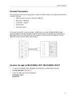
Connecting the Ethernet interface via RJ45:
To connect to a PC, use a straight-through or a cross-over Ethernet cable,
To connect the switch to an Ethernet device, use UTP (Unshielded Twisted Pair) or STP
(Shielded Twisted Pair) Ethernet cables.
Summary of Contents for MLB-E4203-28-F
Page 1: ...MLB E4203 28 F MLB E4204 28 G F 28 Ports L2 Managed Gigabit Switch USER MANNUAL ...
Page 4: ...CONTENTS ii ...
Page 5: ...1 Preface Scope Audience Safety Instructions Documentation Conventions ...
Page 6: ...2 ...
Page 8: ...Preface 4 ...
Page 9: ...5 Overview Overview Panel Introduction Technical Specifications ...
Page 10: ...6 ...