background image

                                                                                                      Inno Pocket Spot Pearl MJ-1025 User Manual ver1.0 

www.mjledlighting.com


15


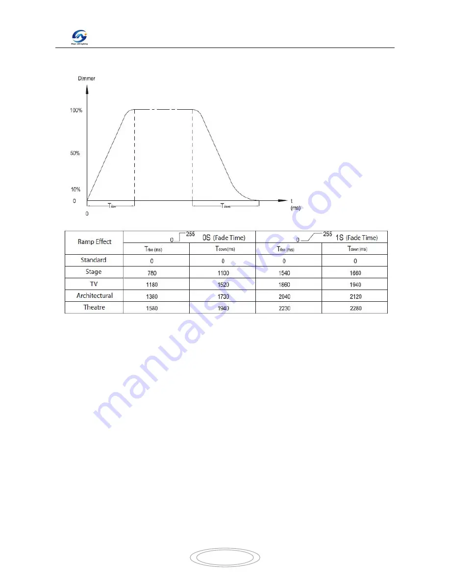
Dimmer Curve Chart 


Fuse Replacement 

Locate  and  remove  the  unit’s  power  cord.  Once  the  cord  has  been  removed  located  the  fuse  holder  located 
inside  the  power  socket.  Insert  a  flat-head  screw  driver  into  the  power  socket  and  gently  pry  out  the  fuse 

holder. Remove the bad fuse and replace with a new one. The fuse holder has a built-in socket for a spare fuse 

be sure not to confuse the spare fuse with active fuse. 


Cleaning 

Due to fog residue, smoke, and dust cleaning the internal and external optical lenses and mirror should be carried 

out  periodically  to  optimize  light  output.  Cleaning  frequency  depends  on  the  environment  in  which  the  fixture 

operates  (I.e.  smoke,  fog  residue,  dust,  dew).  In  heavy  club  use  we  recommend  cleaning  on  a  monthly  basis. 

Periodic cleaning will ensure longevity, and crisp output. 

1. Use normal glass cleaner and a soft cloth to wipe down the out- side casing. 

2. Use a brush to wipe down the cooling vents and fan grill. 

3. Clean the external optics with glass cleaner and a soft cloth every 20 days. 

4. Clean the internal optics with glass cleaner and a soft cloth every 30-60 days. 

5. Always be sure to dry all parts completely before plugging the unit back in. 

Summary of Contents for MJ-1025

Page 1: ...ket Spot Pearl MJ 1025 INSTRUCTION MANUAL Thank you for choosing our LED mini spot moving head light For the sake of your safety Please read and follow these instructions carefully and keep this manual in a safe place for future reference ...

Page 2: ...the separation condition Every unit is tested completely and packed properly by the manufacturer Please make sure the packing and the unit are in good condition before installation and use Should there be any damage caused by transportation consult your dealer and do not use the unit Any damage caused by improper use will not be assumed by the manufacturer or dealer Attention Unceasingly carries o...

Page 3: ...ge and frequency of power supply match the power requirements of the projector It is essential that each projector is correctly earthed and that electrical installation conforms to all relevant standards Do not connect this device to any other types of dimmer apparatus Make sure that the power cord is never crimped or damaged by sharp edges Never let the power cord come into contact with other cab...

Page 4: ...ion yourself The installation should be checked by a skilled person once a year The Inno Pocket Spot Pearl is fully operational in two different mounting positions hanging upside down from a ceiling or set on a flat level surface To avoid internal damage to the unit never mount the unit on its side as illustrated above Be sure this fixture is kept at least 0 5m away from any flammable materials de...

Page 5: ...nywhere DMX 512 DMX is short for Digital Multiplex This is a universal protocol used by most lighting and controller manufactures as a form of communication between intelligent fixtures and controllers A DMX controller sends DMX data instructions from the controller to the fixture DMX data is sent as serial data that travels from fixture to fixture via the DATA IN and DATA OUT XLR terminals locate...

Page 6: ... making your own cables be sure to use standard 110 120 Ohm shielded cable This cable may be purchased at almost all professional sound and lighting stores Your cables should be made with a male and female XLR connector on either end of the cable Also remember that DMX cable must be daisy chained and cannot be split Notice Be sure to follow figures two and three when making your own cables Do not ...

Page 7: ...ransmission in place of 3 pin 5 pin DMX fixtures may be implemented in a 3 pin DMX line When inserting standard 5 pin data cables in to a 3 pin line a cable adaptor must be used these adaptors are readily available at most electric stores The chart below details a proper cable conversion System Menu DMX 512 Address setting Channel Mode Show Mode Dimmer Mode ...

Page 8: ...MENU button for at least 3 seconds To exit without making any adjustments press the MENU button The display will lock after 30 seconds press the MENU button for 3 seconds to unlock ADDR DMX Address Setting 1 Press the either the MENU UP or DOWN buttons until ADDR is displayed press ENTER 2 The current address will now be displayed and flashing Press the UP or DOWN buttons to find your desired addr...

Page 9: ...mer curve and press ENTER to confirm and exit SLND This will let you set unit as a master or slave in a master slave configuration 1 Press the MENU button until SLND is displayed press ENTER Either MAST SL 1 or SL 2 will be displayed 2 Press the UP or DOWN buttons until your desired setting is displayed press ENTER to confirm NOTE In a Master Slave configuration you can set one fixture to Master a...

Page 10: ...ch to have the LED display switch off after 10 seconds 3 Press ENTER to confirm To make you LED display reappear again press any button DISP This function will reverse the display 180º 1 Press the MENU button until DISP is displayed press ENTER 2 Press ENTER to flip the display Press ENTER to flip it again Press ENTER when you have made your desired setup TEST This function will run a self test pr...

Page 11: ...ton for one second to exit OCOL adjustment for the color wheel 1 Press the ENTER button for at least 3 seconds then press the UP or DOWN buttons so that OCOL is displayed press ENTER 2 Use the UP and DOWN buttons to make your adjustments and then press ENTER to confirm Press the MENU button for one second to exit Operation Universal DMX Control This function allows you to use a Elation universal D...

Page 12: ... unit can act as a Master or as a Slave 1 Using approved DMX data cables daisy chain your units together via the XLR connector on the rear of the units Remember the Male XLR connector is the input and the Female XLR connector is the output The first unit in the chain master will use the female XLR connector only The last unit in the chain will use the male XLR connector only For longer cable runs ...

Page 13: ...d this button the unit will begin to strobe COLOR Press this button to enter Dimmer mode Use the 1 9 buttons to select your desired color Adjust the output intensity using the DIMMER and DIMMER buttons 1 9 When in either Gobo mode or Color mode these buttons will allow you to select either a gobo or color SOUND ON OFF These buttons activate and deactivate the sound active mode SHOW This activates ...

Page 14: ... 240 247 248 255 Close Open Strobe Slow Fast Open Fast Close Slow Open Open Fast Open Slow Close Open Random Strobe Open 6 8 CH Dimmer 000 255 0 100 7 9 CH Pan Tilt Speed 000 255 Fast Slow 8 CH 10 CH Function 000 069 070 079 080 089 090 099 100 109 110 119 120 199 200 209 210 249 250 255 Null Blackout while Pan Tilt Move Null Blackout when Color changes Null Blackout when Gobo changes Null Reset A...

Page 15: ... dust cleaning the internal and external optical lenses and mirror should be carried out periodically to optimize light output Cleaning frequency depends on the environment in which the fixture operates I e smoke fog residue dust dew In heavy club use we recommend cleaning on a monthly basis Periodic cleaning will ensure longevity and crisp output 1 Use normal glass cleaner and a soft cloth to wip...

Page 16: ... may not activate the unit Specifications Model MJ 1025 Voltage 100 240V 50 60Hz LED 1 x 12W White LED Power Consumption 26W 120V 27W 230V Dimensions 6 25 L x 5 75 W x 10 5 H 159mm x 147mm x 265mm Weight 7 Lbs 3 kgs Beam Angle 13 Degrees Fuse 3 Amp Duty Cycle None DMX 2 DMX Channel Modes 9 Channel Mode 11 Channel Mode Colors 7 White Gobos 7 Spot Sound Active Yes Working Position Any Safe Secure Po...

Reviews: