


Document No.: E20-018-00
10
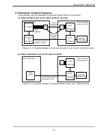
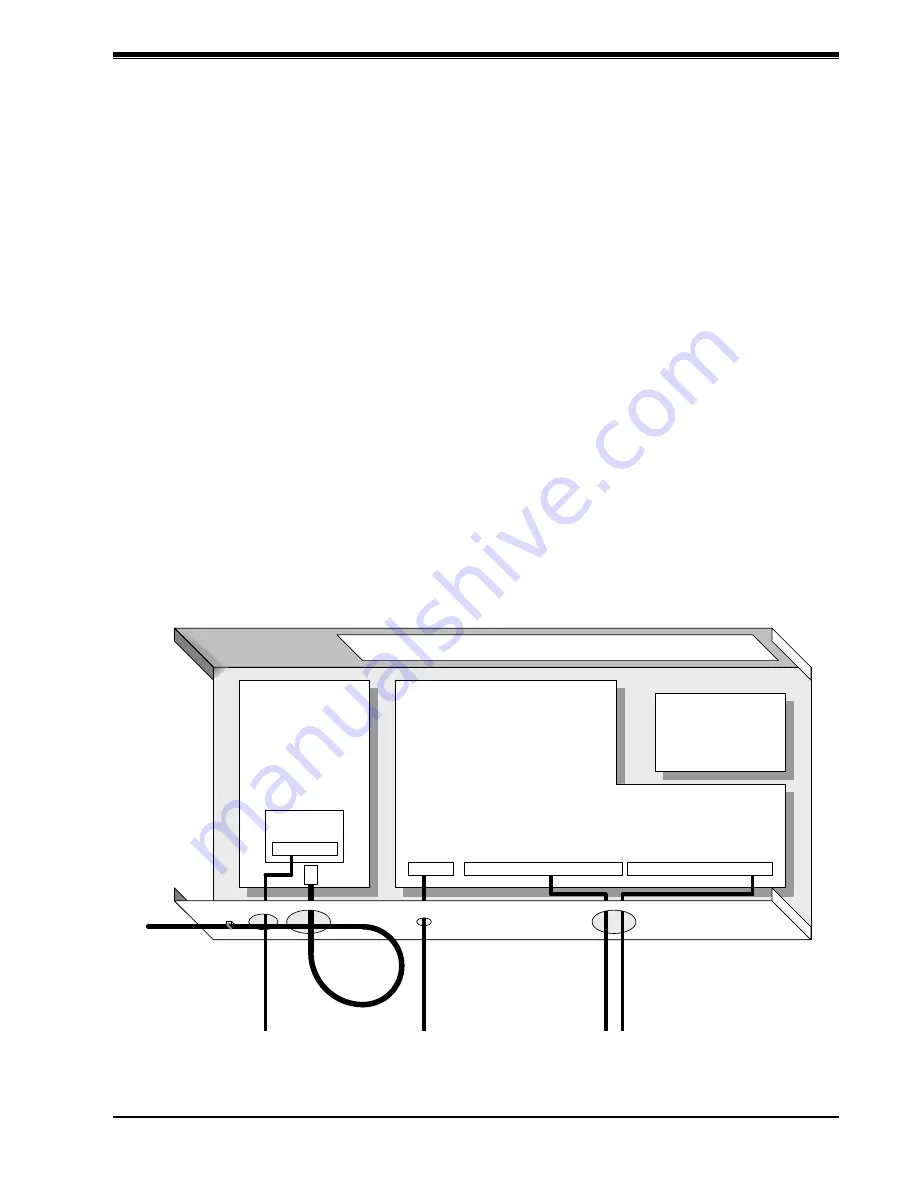
Signal wire
M-NET3
communication
line wire
CPU board
EC11
OPR board
Switching power
supply
I/O board
RS-422 communication
line wire
Steam pressure
sensor wire
Power supply wire
6.
WIRING
6.1.
Precautions
(1) Wiring of power supply wires
• Use a wire with 2.0 mm
2
or larger diameter for the power supply and crimp ring tongue
terminals.
• Connect the grounding phase of the power supply to the N phase. Be sure to ground the
equipment grounding terminal using a wire with a diameter equal to or larger than the
power supply wire diameter.
Provide Japanese D-type grounding
(*)
or better.
(2) Wiring of signal wires
• The wires used as signal wires and terminal processing must conform to “6.4 Wires for
Use”.
• Be sure to separate the signal wires, sensor wires, and input/output signal wires from
power output wires and power supply wires. Do not install them in the same conduit. Do
not install signal wires in a location where magnetic and electric fields are generated by
machine tools or next to high-output machinery.
• To mark the wires, use stamped mark tubes or mark bands.
6.2.
Wiring Procedures
Perform wiring by passing each wire through the specified wire inlet.
Figure 6-1: EJ-210 wiring procedures