4
- 58
4.6 Redundant-CPU-Compatible Function
4.6.1 Overview of redundant system operation
4
FUNCTIONS
4.6
Redundant-CPU-Compatible Function
This section explains the case of using the CC-Link IE controller network module with
Redundant CPUs.
4.6.1
Overview of redundant system operation
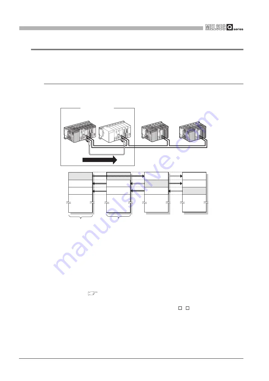
(1) Cyclic transmission processing
1) A redundant system is composed of system A and system B, and the same
send ranges for respective stations in link devices (LB/LW) are set for stations
of systems A and B.
*1
2) The station acting as the control system sends and receives cyclic data.
3) The station acting as the standby system only receives cyclic data.
4) The source CPU-side-device data in the own station's send range in the link
devices (LB/LW) must be tracking-transferred.
*2*3
For details of tracking transfer, refer to the following manual.
QnPRHCPU User's Manual (Redundant System)
* 1 Pairing is not available for communication by LX/LY.
* 2 Tracking transfer is not available for link direct devices (J
\
).
* 3 Do not use tracking transfer for the link special relay (SB0020 to SB01FF) and link special register
(SW0020 to SW01FF) that are turned ON/OFF by the system.
Figure 4.66 Cyclic transmission processing
Redundant system
Tracking cable
4) Tracking transfer
Normal station
No.3
Normal station
No.4
Link relay (LB)
LB0
LB7FFF
No.1, 2 send range
No.3
No.4
No.1, 2
No.3 send range
No.4
No.1, 2
No.3
No.4 send range
No.3
No.4
1) 2)
1) 3)
System A
(control system)
Control station
No.1
System B
(standby system)
Normal station
No.2
Summary of Contents for QJ71GP21-SX
Page 1: ......
Page 2: ......
Page 644: ...App 94 Appendix 6 External Dimensions Appendix 6 2 QJ71GP21S SX APPENDICES Memo ...
Page 649: ......
Page 650: ......


