


3
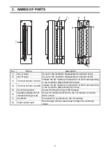
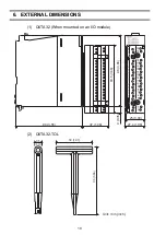
3. NAMES OF PARTS
No.
Name
Description
1)
Line A cover
Cover for the insulation displacement connector line A
2)
Line B cover
Cover for the insulation displacement connector line B
3)
Terminal number (Line A)
Indicate the I/O module pin number A1 to A20 corresponding
to the insulation displacement terminals.
4)
Terminal number (Line B)
Indicate the I/O module pin number B1 to B20 corresponding
to the insulation displacement terminals.
5)
Cover fixing screw
Screw for fixing the cover (M2.6 screw)
6)
Insulation displacement
connector fixing screw
Screw for fixing the Q6TA32 to the I/O module connector
(M2.6 screw)
7)
Connector
Connector for connection to the I/O module.
8)
Tester lead-in port
Hole through which a tester lead is drawn for continuity
check.
2)
3)
4)
5)
6)
7)
8)
1)