


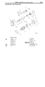
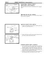

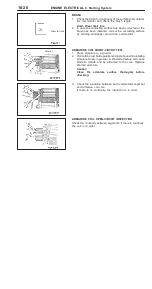


ENGINE ELECTRICAL ±
Ignition System
16-27
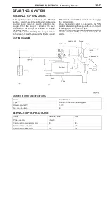
IGNITION SYSTEM
GENERAL INFORMATION
This system is equipped with four ignition coils with
built-in power transistors for each of the cylinders.
Interruption of the primary current flowing in the
primary side of an ignition coil generates a high
voltage in the secondary side of the ignition coil.
The high voltage thus generated is applied to the
spark plugs to generate sparks.
The engine-ECU turns the power transistors inside
the ignition coils alternately on and off. This causes
the primary currents in the ignition coils to be
alternately interrupted and allowed to flow to fire
the cylinders in the order 1 ± 3 ± 4 ± 2.
The engine-ECU determines which ignition coil
should be controlled by means of the signals from
the camshaft position sensor and the crank angle
sensor. It also detects the crankshaft position, in
order to provide ignition at the most appropriate
timing in response to the engine operation
conditions.
When the engine is cold or running at high altitudes,
the ignition timing is slightly advanced to provide
optimum performance. Furthermore, if knocking
occurs, the ignition timing is gradually retarded until
knocking ceases.
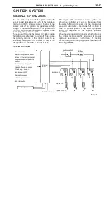
SYSTEM DIAGRAM
Engine-
ECU
Air flow sensor
Barometric pressure sensor
Intake air temperature sensor
Engine coolant temperature
sensor
Accelerator pedal position
switch
Camshaft position sensor
Crank angle sensor
Ignition switch-ST
Detonation sensor
Vehicle speed sensor
Inhibitor switch
Ignition switch
Battery
Ignition coil
Spark plug
Cylinder No.
To tachometer
4
3
2
1
A/T-ECU
Summary of Contents for Pajero Pinin 1999
Page 32: ...NOTES ...
Page 73: ...13A 1 FUEL CONTENTS GASOLINE DIRECT INJECTION GDI 13A FUEL SUPPLY 13B ...
Page 190: ...NOTES ...
Page 191: ...13B 1 FUEL SUPPLY CONTENTS FUEL TANK 2 Fuel Pump Module 4 ...
Page 214: ...NOTES ...
Page 222: ...NOTES ...
Page 256: ...NOTES ...
Page 274: ...NOTES ...
Page 282: ...NOTES ...
Page 360: ...NOTES ...
Page 412: ...NOTES ...
Page 443: ...32 1 POWER PLANT MOUNT CONTENTS ENGINE MOUNTING 2 TRANSMISSION MOUNTING 3 ...
Page 446: ...NOTES ...
Page 447: ......
Page 448: ......
Page 449: ......
Page 450: ......
Page 451: ......
Page 452: ......
Page 453: ......
Page 454: ......
Page 455: ......
Page 456: ......
Page 457: ......
Page 458: ......
Page 459: ......
Page 460: ......
Page 461: ......
Page 467: ...NOTES ...
Page 468: ...BASIC BRAKE SYSTEM 35A ANTI SKID BRAKING SYSTEM ABS 4WD 35B 35A 1 SERVICE BRAKES CONTENTS ...
Page 499: ...NOTES ...
Page 531: ...NOTES ...
Page 541: ...NOTES ...
Page 649: ...NOTES ...
Page 728: ...54A 1 CHASSIS ELECTRICAL CONTENTS CHASSIS ELECTRICAL 54A SMART WIRING SYSTEM SWS 54B ...
Page 883: ...NOTES ...
Page 919: ...NOTES ...


