Mitsubishi P93DE Operation Manual Download Page 5

INSTRUCTIONS FOR MEDICAL USE

<according to the Medical Safety/EMC standard IEC/EN 60601-1-2>

MEDICAL ELECTRICAL EQUIPMENT needs special precautions regarding EMC and needs
to be installed and put into service according to the EMC information provided in the AC-
COMPANYING DOCUMENTS.
Portable and mobile RF communications equipment can affect MEDICAL ELECTRICAL
EQUIPMENT.

Technical description

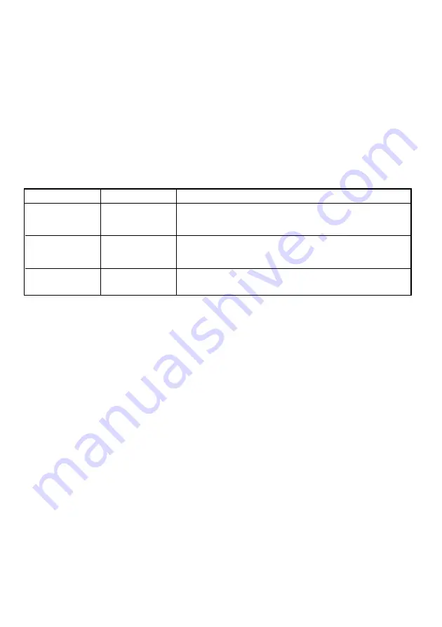
List of all cables and maximum length of the cable and transducers and other
ACCECCORIES

AC power cord

USB cable

Thermal paper

Maximum length

2.5 m

2 m

Reference page in this operation manual

This page, the previous pages for safety and page 22
for accessories

This page, the previous pages for safety and page 22
for accessories

Page 3 for thermal paper, Page 22 for accessories

WARNING:

The use of ACCESSORIES, transducers and cables other than those specified, with the
exception of transducers and cables sold by the manufacturer of the Model P93DW/P93DE
as replacement parts for internal components, may result in increased EMISSIONS or
decreased IMMUNITY of the Model P93DW/P93DE.

WARNING:

The Model P93DW/P93DE should not be used adjacent to or stacked with other equipment
and that if adjacent or stacked use is necessary, the Model P93DW/P93DE should be
observed to verify normal operation in the configuration in which it will be used.

Summary of Contents for P93DE

Page 1: ...iness and light industrial premises and on small scale enterprises inside as well as outside of the buildings All places of operation are characterised by their connection to the public low voltage po...

Page 2: ...eceptacle of the host equipment The AC power cord should be UL or CSA approved and consist of type SJT size 16 or 18AWG length 2 5m or shorter cord with IEC320 C13 type 250V 10A or higher rating conne...

Page 3: ...item may be hot and should not be touched The ON OFF symbol indicates connection to or disconnection from the mains at least for mains switches The Equipotentiality symbol identifies the terminals co...

Page 4: ...EN60950 Connect to the 230V receptacle of the room or the host equipment The AC power cord should be VDE approved and consist of core size 1mm2 or bigger length 2 5m or shorter cord with IEC320 C13 t...

Page 5: ...is operation manual This page the previous pages for safety and page 22 for accessories This page the previous pages for safety and page 22 for accessories Page 3 for thermal paper Page 22 for accesso...

Page 6: ...ips short interruptions and voltage variations on power supply input lines IEC EN 61000 4 11 Power frequency 50 60 Hz magnetic field IEC EN 61000 4 8 IEC EN 60601 test level 6 kV contact 8 kV air 2 kV...

Page 7: ...electromagnetic site survey a should be less than the compliance level in each frequency range b Interference may occur in the vicinity of equipment marked with the following symbol Compliance level...

Page 8: ...smitter W 0 01 0 1 1 10 100 150 kHz to 80 MHz d 1 2 P 0 12 0 38 1 2 3 8 12 80 MHz to 800 MHz d 1 2 P 0 12 0 38 1 2 3 8 12 800 MHz to 2 5 GHz d 2 3 P 0 23 0 73 2 3 7 3 23 For transmitters rated at maxi...

Page 9: ...Panel 7 5 5 5 5 5 INSTALLATION OF PAPER 8 9 6 6 6 6 6 EXAMPLE OF CONNECTION SETTING OF SWITCHES 10 7 7 7 7 7 PRINTING 11 12 8 8 8 8 8 ADJUSTMENT OF PRINT PICTURE 13 15 9 9 9 9 9 ERROR DISPLAY 16 18 A...

Page 10: ...warmer one dew is likely to be formed If dew is formed printing is not possible OPERATING AMBIENT TEMPERATURE RANGE The operating ambient temperature range is 5 C 40 C 41 F 104 F and humidity of 20 80...

Page 11: ...ENCE Turn off the MAIN power switch and unplug the power cord during a long absence THERMAL PAPER 2 Thermal papers listed in the page of SPECIFICA TIONS are available 2 When the remaining length of th...

Page 12: ...the instructions for use Any service after expiration of the warranty period will be chargeable Consult your dealer for advice TECHNICAL DESCRIPTION The supplier will make available on request such c...

Page 13: ...ke sure to keep the unit horizontal 3 3 3 3 3Take the unit out of the box carefully Take the unit out of the box by the following procedures Make sure to check the contents 4 4 4 4 4 Unwrap the unit A...

Page 14: ...rast button 14 6 Locks the button functions 5 UP button 11 14 16 19 10 13 13 1 Makes fine adjustments of the bright ness and contrast of the print image DOWN button Press to decrease the setting value...

Page 15: ...o this unit For details refer to the installation instruction of equipment to be connected D E C F Name Function 10 DIP switch Selects special functions Connects to the device equipped with USB interf...

Page 16: ...sitive side printing side up When the paper roll is placed inversely images can not be printed OPEN Switch the lever located on the left side to the OPEN position The door opens printing side Place th...

Page 17: ...ed out skewed from the print exit adjust the paper position so that it is fed out straight Do not allow slack in the paper roll Set the paper tightly to remove any slack Ifthesideoftheprintpaperisunev...

Page 18: ...nected with this printer The printer driver for Windows 2000 XP is supplied with this printer Refer to the Read me for installing the printer driver in the CD ROM supplied with this unit 2 2 2 2 2 How...

Page 19: ...ed 2 When pressing the UP button during copy printing continuous printing is available 1 Turn on the power 3 Cut the printed paper 2 Print a picture displayed on the screen Copy Printing Press the POW...

Page 20: ...heated and the indicator blinks In this case wait for a while until the unit has cooled down Avoid pulling out or holding the paper during printing or copying to prevent paper jam Do not touch the pap...

Page 21: ...T button BRT CONT UP button UP and DOWN button DOWN 1 Press the BRT CONT button OPEN COPY FEED LOCK UP DOWN BRT CONT BRT CONT LOCK Press the BRT CONT button BRT CONT once to adjust the printer brightn...

Page 22: ...s memorized The memorized value will not be lost even when the power is turned off Press the UP button to increase the value 3 Store the set value Press the DOWN button to decrease the value The setti...

Page 23: ...at was set before change While adjusting the printer brightness or printer contrast Locking the button functions You can lock the function of UP and DOWN buttons on the control panel To lock the butto...

Page 24: ...lved If some images are waiting to be processed the following buttons function as described below COPY button Each time the COPY button is pressed the number displayed by the indicator increases as Af...

Page 25: ...or there are images waiting to be processed an alarm tone is heard Then the paper is fed automati cally about 15 cm and printing resumes After the error is resolved the unit resumes printing from the...

Page 26: ...rupted image and finishes printing all the outstanding images Symptom When the thermal head does not automatically go down at the start of printing or paper feeding an alarm tone is heard When the the...

Page 27: ...mode Printer contrast mode Error detect state Power off During data receiving During data receiving Fine adjustment of the picture brightness No paper Button input error Door is open Gear lock Fine ad...

Page 28: ...ng paper 7 7 7 7 7 Repeat the steps 3 3 3 3 3 6 6 6 6 6 by 2 or 3 times and print 1 2 sheets to verify the cleaning effect 4 4 4 4 4 Close the door 5 5 5 5 5 Press the FEED button 6 6 6 6 6 Take out t...

Page 29: ...y appear on the print In this case eliminate the dust on to the rubber roller with a blower or a brush The regular cleaning using a lint free cloth etc which is moistened with ethyl alcohol is recomme...

Page 30: ...C Humidity 20 80 RH No dewing External dimensions 6 1 x 3 5 x 10 1 154mm x 89 5mm x 256mm W x H x D Weight 6 2 lbs 2 8 kg Standard accessories AC power cord 1 piece Thermal paper KP65HM CE 1 roll Cle...

Page 31: ...fach 1548 40835 Ratingen Germany Phone 02102 486 9250 FAX 02102 486 7320 French Branch 25 Boulevard des Bouvets 92741 NANTERRE cedex Phone 01 55 68 55 00 FAX 01 55 68 57 31 Italian Branch Centro Direz...

Reviews: