Mitsubishi MR-385R-ST-A Service Manual Download Page 20

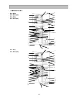
6.5  Importance detail of fault analysis

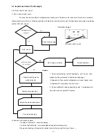
6.5.1 Flow chart of self - check
1) Self - check monitor circuit

For show the fault condition of refrigerator and clarify point. Therefore, self - check monitor control is provided 

that are able to monitor No. of blinking condition with electric circuit and electric part . Before disconnect power plug please
confirm LED self - check .

"CONTROL PANEL"

LED show shelf - check

Caution

1. As the part list below couldn't analysis by  self - check , then 
please check by reference to trouble shooting page.
- Dilapidation of door switch ,refrigerator room and freezer room.
- Dilapidation of compressor and fan motor .
2. If have malfunction when supply the power . Compressor and 
fan motor will not operate 20 minutes.

2) Interval of self check analysis

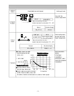
- Troubles of thermistor : will check always.
- Trouble of defrost heater : will just analyse during defrost display only.
(The period checking will analyse the defrost circuit after connect the plug 2 hours  )

- 19 -

Refrigerator plug 

connect?

Connect power plug

Self - check

Mal Function Display

(No .of blinking)

No change on display

Normal operation

Check the fault point as 

malfunction list

Disconnect power plug

Repair the macfunction cause

Connect power plug

No

Yes

Yes

No

Summary of Contents for MR-385R-ST-A

Page 1: ...UIT 5 NAME OF THE PARTS 6 TROUBLE SHOOTING 6 1 TROUBLE CRITERION OF MAIN PARTS 6 2 HOW TO CHECK P C BOARDS 6 3 TEST POINT DIAGRAM OF MAIN CONTROL BOARD 6 4 MULFUNCTION DISPLAY AND CHECKING POINT 6 5 I...

Page 2: ...air flow front air flow Evaporator Fin and tube type Condenser Concealed type Defrost system Automatic Heater defrost Drain Automatic drainage Temperature control system Automatic control Refrigerato...

Page 3: ...air flow front air flow Evaporator Fin and tube type Condenser Concealed type Defrost system Automatic Heater defrost Drain Automatic drainage Temperature control system Automatic control Refrigerator...

Page 4: ...ir flow front air flow Evaporator Fin and tube type Condenser Concealed type Defrost system Automatic Heater defrost Drain Automatic drainage Temperature control system Automatic control Refrigerator...

Page 5: ...ter Defrost heater Deodorition Model Type Number of poles Input W Revolution r p m Model Freezer Refrigerator MM1 6177 Dial position ON OFF OPEN SHUT Warmer o C 13 7 19 0 3 5 Normal o C 16 9 22 9 MAX...

Page 6: ...Deodorition Model Type Number of poles Input W Revolution r p m Model Freezer Refrigerator MM1 6177 Dial position ON OFF OPEN SHUT Warmer o C 13 7 19 0 3 5 Normal o C 16 9 22 9 MAX 5 0 1 0 1 5 Colder...

Page 7: ...er Deodorition Model Type Number of poles Input W Revolution r p m Model Freezer Refrigerator MM1 6177 Dial position ON OFF OPEN SHUT Warmer o C 13 7 19 0 3 5 Normal o C 16 9 22 9 MAX 5 0 1 0 1 5 Cold...

Page 8: ...Unit mm MR 385R A MR 385R A NZ 7 2 OUTLINES AND DIMENSIONS 20 685 20 1334 454 40 100 1591 700 REQUIRED SPACE FOR INSTALLATION 1950 PLUG CORD LENGTH 568 685 8 1591 942 73...

Page 9: ...Unit mm MR 420R A MR 420R A NZ 8 PLUG CORD LENGTH REQUIRED SPACE FOR INSTALLATION 20 685 20 1334 454 40 100 1696 700 1950 568 685 8 1696 1047 73...

Page 10: ...Unit mm MR 455R A MR 455R A NZ 9 PLUG CORD LENGTH REQUIRED SPACE FOR INSTALLATION 20 685 20 1334 454 40 100 1806 700 1950 568 685 8 1806 1157 73...

Page 11: ...SKELETON WIRING DIAGRAM MR 385R A MR 385R A NZ MR 420R A MR 420R A NZ MR 455R A MR 455R A NZ ACTUAL WIRING DIAGRAM 3 WIRING DIAGRAM 10...

Page 12: ...MR 385R A MR 420R A MR 385R A NZ MR 420R A NZ 11 4 REFRIGERANT CIRCUIT...

Page 13: ...MR 455R A MR 455R A NZ 12...

Page 14: ...MR 385R A MR 385R A NZ MR 420R A MR 420R A NZ MR 455R A MR 455R A NZ 13 5 NAME OF PARTS...

Page 15: ...W Rated input Compressor in Opened 69 9 o C Motor protector 120 5o C 14 33 Approx Connected Point Model Normal abnormal faulty Less than 1 Opened or Short 0 rear side of the frame Starting current Run...

Page 16: ...l panel of the refrigerator 2 Out of the above range compartment abnormal Thermistor Check Procedure Thermistor resistance will vary with the change of temperature o C Take the temperature around the...

Page 17: ...and resistance using 8 connectors outside the box How to check with connectors 1 Check for 230 240V output during power on POWER ON Make the pin No 7 9 of the 9 pins white connector as a common pin an...

Page 18: ...6 3 TEST POINT DIAGRAM OF MAIN CONTROL BOARD MR 385R A MR 420R A MR 455R A MR 385R A NZ MR 420R A NZ MR 455R A NZ 17...

Page 19: ...comp had been off more than 20 min Improve in contact Improve in contact 1 Check connector of control PCB CN1 relay connector temp fuse 3 2 1 Improve in contact LED display self check Malfunction dis...

Page 20: ...hooting page Dilapidation of door switch refrigerator room and freezer room Dilapidation of compressor and fan motor 2 If have malfunction when supply the power Compressor and fan motor will not opera...

Page 21: ...eezer Defrost heater and Drip tray 6 out of base after remove heater cover plate and drip tray Caution on assembly 7 1 Insert the fan into the base of fan motor s shaft check if the fan rotates with y...

Page 22: ...m tape and sealing tape remove PC Board Photo 7 5 Remove duct R assy damper thermo is installed within it Photo 7 Remove the screw of damper thermo Caution on assembly 1 Be sure to use new sealing mat...

Page 23: ...ection of the discharge pipe and suction pipe 5 Replace the compressor and the dryer at a time The dryer should be the one packed with the compressor CAUTION ON ASSEMBLY After replacement check coolin...

Page 24: ...DOOR BODY PARTS MR 385R A MR 385R A NZ MR 420R A MR 420R A NZ MR 455R A MR 455R A NZ 23 8 PARTS LIST 1 2 3 4 5 6 10 9 11 7 8 1 2 4 5 10 9 11 8 7 6 3...

Page 25: ...1 1 1 1 1 1 KIEJ81000 1 1 KIEJ82000 1 1 KIEJ83000 1 1 KIEJ84000 1 1 KIEJ85000 1 1 KIEJ86000 1 1 KIEH79110 1 1 1 1 KIEH82110 1 1 1 1 KIEH85110 1 1 1 1 11 KIEG05741 CATCHER 1 1 1 1 1 1 1 1 1 1 1 1 KIEJ...

Page 26: ...5R A NZ MR 420R A MR 420R A NZ MR 455R A MR 455R A NZ 25 1 2 3 4 5 6 7 17 18 22 23 25 9 8 10 11 12 13 30 22 31 27 26 14 15 19 20 21 24 29 28 1 2 3 4 6 7 8 10 12 13 14 15 29 30 31 28 22 27 26 25 24 23...

Page 27: ...KIEJ82705 1 1 1 1 1 1 18 KIEJ81701 HINGE ASSY UPPER 1 1 1 1 1 1 1 1 1 1 1 1 19 KIEH79431 CRYSTAL SHELF F 1 1 1 1 1 1 1 1 1 1 1 1 20 KIEH79440 ICE TRAY 1 1 1 1 1 1 1 1 1 1 1 1 21 KIEH79467 ICE BOX 1 1...

Page 28: ...ELECTRICIAL PARTS AND UNIT PARTS MR 385R A MR 385R A NZ MR 420R A MR 420R A NZ MR 455R A MR 455R A NZ 27 1 2 4 3 5 6 9 7 10 8 11 13 12 14 15 16 15 17 18 20 19 27 21 22 23 24 26 25 28 30 29 31...

Page 29: ...MOTOR UDVH15MA1H 1 1 1 1 1 1 1 1 1 1 1 1 17 KIECD4362 FAN SWITCH 1 1 1 1 1 1 1 1 1 1 1 1 18 KIEHD2386 LAMP SOCKET R 1 1 1 1 1 1 1 1 1 1 1 1 19 KIEG01321 FAN 1 1 1 1 1 1 1 1 1 1 1 1 20 KIEA53346 RUNNIN...

Page 30: ...85R A NZ MR 420R A MR 420R A NZ MR 455R A MR 455R A NZ 29 NO STEP ON 1 2 3 L R 1 C F B BOX ASSY 8 C F B TOP COVER 5 SIDE CUSHION ASSY 4 PACKING COVER 7 C F B PALLET 6 BOTTOM CUSHION 3 TOP CUSHION MID...

Page 31: ...1 1 1 1 3 KIEH79972 TOP CUSHION MID 1 1 1 1 1 1 1 1 1 1 1 1 4 KIEG55973 PACKING COVER 1 1 1 1 1 1 1 1 1 1 1 1 5 KIEJ81971 SIDE CUSHION ASSY 1 1 1 1 1 1 1 1 1 1 1 1 6 KIEH79978 BOTTOM CUSHION 1 1 1 1 1...

Page 32: ...OND TECHNOLOGIES LIMITED BDT Wellington Office Head Office Auckland Office Christchurch Office 1 Parliament Street Unit1 4 Walls Road Suite 2 Level 1 PO Box 30 772 Penrose 37 Manderville Street Lower...

Reviews: